An airplane comes into the shop with three write-ups on one work order: the altimeter reads off, the vertical speed indicator jumps, and the airspeed reads a little high. The last shop replaced the altimeter, and nothing changed.
Airspeed indicator
Shows how fast the airplane moves through the air.
Reads a little high
Altimeter
Shows how high the airplane is.
Reads off
Vertical speed indicator
Shows how fast the airplane climbs or descends.
Jumps
FIG 1 The three write-ups on the work order.
Write-up
A pilot’s report of a problem, entered on the work order for the shop.
Pitot-static system
The tube, ports and lines that bring outside air pressure to the airspeed indicator, the altimeter and the vertical speed indicator.
Pitot
Said “PEE-toe.” The system is named for its pitot tube, which faces forward into the air.
Each of these instruments reads air pressure from the lines. When you know which pressure feeds which instrument, you can find the one fault behind several write-ups instead of replacing instruments that work.
Learning Objectives
When you finish this lesson you can do the four things below. The check at the end asks about each of them.
1IdentifyIdentify the pitot tube, static ports, drains, pitot heat and alternate static source, and state the job of each.
2StateState the pressure the pitot tube senses and the pressure the static ports sense.
3NameName the pressure source for the airspeed indicator, the altimeter and the vertical speed indicator, and state what each instrument measures.
4PredictPredict which instruments a leak in the pitot line or in the static line will affect.
The two lines you will follow through this lesson: pitot pressure in amber, static pressure in cyan.
Lecture Video
Watch the lecture. Continue appears when it ends. You can skip it for now and come back to this page later.
Two-Point Readings
In the Voltage lesson you learned that voltage is the pressure of electrons, and that a voltmeter reads the difference in that pressure between its two probes. Look at the meter in the drawing, then answer.
Question
Both voltmeter probes touch the same terminal on a live 28-volt bus. What does the meter read?
This lesson uses the same idea with air. The airspeed indicator reads the difference between two air pressures.
The Six Flight Instruments
Flight instruments are the instruments the pilot uses to fly the airplane. A traditional panel has six of them in a standard pattern: the airspeed indicator, the attitude indicator and the altimeter across the top, and the turn coordinator, the heading indicator and the vertical speed indicator across the bottom. Technicians call this layout the six pack.
Pressure instruments
The six fall into two groups by what drives them. Three of them run on air pressure from the pitot-static system.
Gyro instruments
The other three each contain a gyro, a wheel spun at high speed by air from an engine-driven vacuum pump or by an electric motor. You study them in the Gyro Instruments lesson.
Select the three instruments that run on air pressure.
FIG 2 The six pack, with the magnetic compass above it.
0 of 3 found
Select an instrument on the panel.
The Pitot Tube
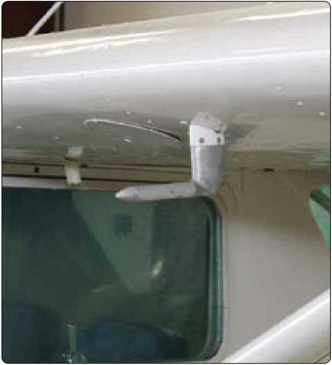
The pitot tube is an open tube, about a quarter inch across at its opening, that points forward into the airflow. Air flowing into it has nowhere to go, so it stops inside the tube, and stopping moving air turns its motion into extra pressure. The pitot line carries that pressure to the airspeed indicator.
FIG 3 A pitot tube on its mast under a wing. Source: FAA-H-8083-31B, Figure 10-24.
Air pressure
The push of the air on every surface it touches, measured in pounds per square inch (psi). At sea level it is about 14.7 psi, and it is lower the higher you climb.
Static pressure
The pressure of the still air around the airplane, also called ambient pressure. It is there whether the airplane moves or sits still.
Dynamic pressure
The extra pressure that motion makes when moving air is stopped. It is zero when the airplane sits in still air, and it grows quickly with speed: twice the speed gives four times the dynamic pressure.
The pitot tube senses ram pressure: static pressure plus dynamic pressure. Ram pressure is also called total or impact pressure.
A knot is one nautical mile per hour.
Static pressure
14.69 psi
Dynamic pressure
0.00 psi
Ram pressure in the pitot line
14.69 psi
The airplane is not moving, so the pitot tube senses static pressure only.
Henri Pitot
Henri Pitot, painting by an unknown artist, before 1800. Public domain, via Wikimedia Commons.
1732
Henri Pitot, French engineer, 1695 to 1771
In 1732 Henri Pitot was given the job of measuring how fast the river Seine flowed. He pointed the open end of a bent tube upstream into the current. The moving water pushed into the tube and stopped, and the water inside the tube rose above the surface of the river. The faster the current, the higher the water rose: double the speed of the current, and the water rose four times as high.
The tube on every airplane does the same job with air instead of water, and it still carries his name.
FIG 4 Pitot’s bent tube. Twice the current, four times the height.
Slow current: the water rises 1 mark above the river surface.
The Static Ports
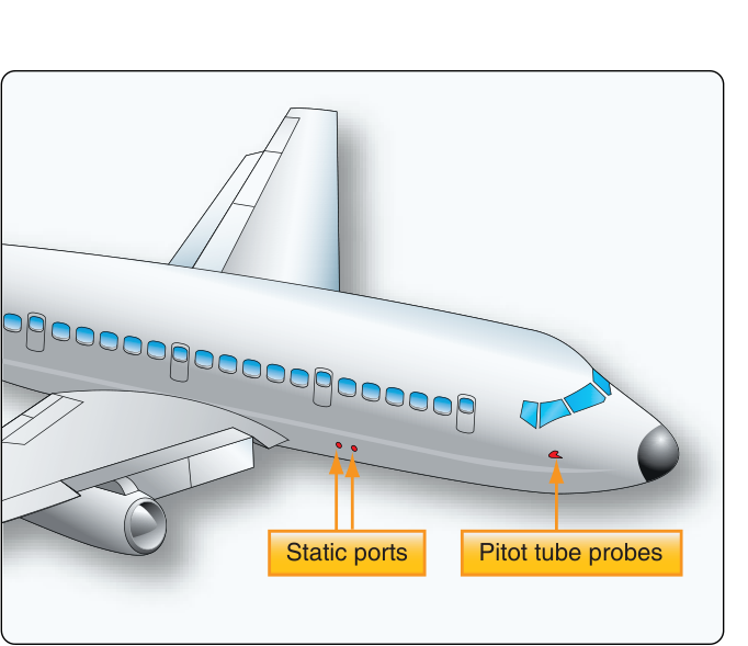
A static port is a small hole set flush with the skin on the side of the fuselage. The air slides past the hole without pushing into it, so the port senses static pressure alone. That pressure falls as the airplane climbs and rises as it descends, and the airplane’s speed does not change it.
FIG 5 Static ports and pitot tube probes on an airliner. The static ports are placed where the airflow disturbs them least, to keep altimeter error small. Source: FAA-H-8083-31B, Figure 10-37.
Most light airplanes have one static port on each side of the fuselage, usually behind the cabin. A tee, a fitting shaped like the letter T, joins the two into one static line. When the airplane flies slightly sideways, called a sideslip, the air pushes harder on one port and less on the other, and the joined line gets the average of the two.
Left port
Right port
Static line
Both ports sense the same static pressure.
On some airplanes the static holes are on the side of the pitot tube itself; that part is called a pitot-static tube.
Question
Ram pressure in the pitot tube is static pressure plus dynamic pressure. Which part does a static port sense by itself?
The Pitot-Static System
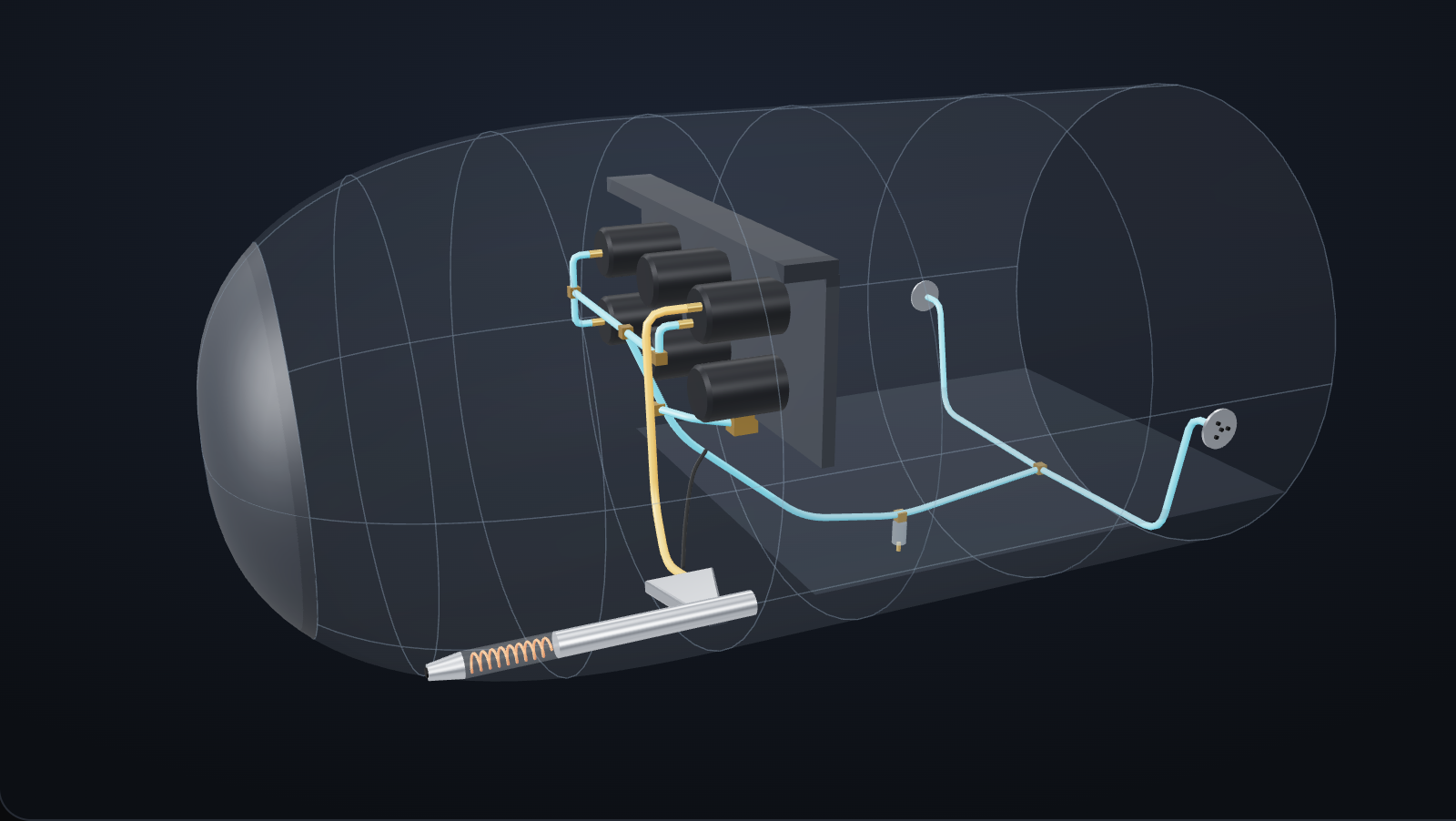
The pitot tube and the static ports each feed a line, a small aluminum or plastic tube that carries their pressure to the instruments behind the panel. Each line ends at a fitting, a threaded connector on the back of an instrument. The pitot line goes to one instrument. The static line branches to all three.
Choose a line to follow its pressure, or select a numbered part. Drag to turn the model; pinch or scroll to zoom.
Pitot pressureStatic pressure
This device cannot show the 3D model, so a picture of it is shown. The numbered parts and the line buttons still work.
Choose a line, or select a numbered part.
FIG 6 The nose of a light twin-engine airplane, where the pitot tube is mounted on the fuselage, with the skin made clear to show the lines.
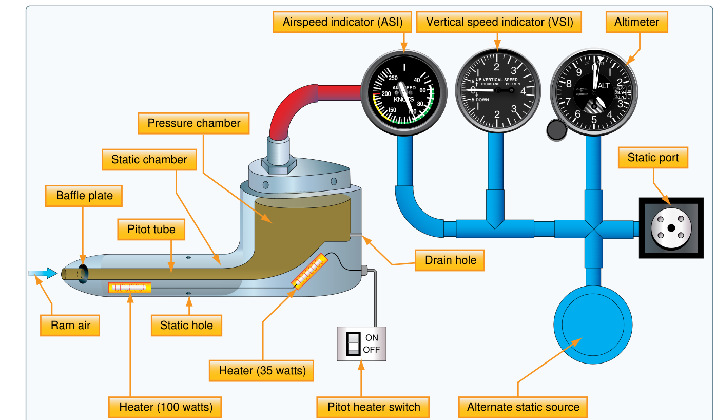
FIG 7 The FAA’s drawing of a pitot-static system. Its pitot tube also has static holes and a heater; the separate static port and the alternate static source feed the same static line. Source: FAA-H-8083-25B, Figure 8-1.
The Airspeed Indicator
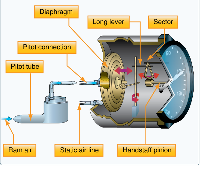
The airspeed indicator is a differential pressure gauge: it measures the difference between two pressures. Inside its sealed case is a diaphragm, a thin metal capsule that swells when the pressure inside it is higher than the pressure around it. The pitot line feeds the inside of the diaphragm, and the static line fills the case around it.
Ram pressure (inside) minus static pressure (around it) leaves the dynamic pressure. That difference moves the needle.
Static pressure pushes on both sides of the diaphragm, so it cancels. Only the dynamic pressure, which comes from the airplane’s motion, moves the diaphragm, and a linkage of levers and gears turns the needle. On a parked airplane in still air, the pressures inside and outside the diaphragm are equal, and the needle rests on zero.
Pitot line (inside the diaphragm)
14.69 psi
Static line (the case)
14.69 psi
Difference
0.00 psi
Both sides are equal, so the difference is zero and the needle rests on zero.
FIG 8 Inside an airspeed indicator. Select a number. Source: FAA-H-8083-25B, Figure 8-7.
Select a number on the figure.
The Altimeter
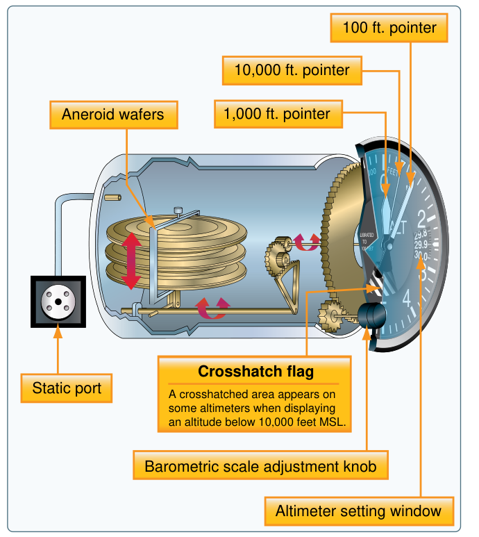
The altimeter is a pressure gauge with a scale marked in feet. Inside its sealed case is a stack of aneroid capsules, metal capsules sealed with most of the air removed. The static line fills the case around them. As the airplane climbs, static pressure falls, the capsules expand, and gears turn the pointers. Only the static line reaches the altimeter.
About half
At 18,000 feet
The air pressure at 18,000 feet is 7.34 psi, about half of the 14.69 psi at sea level.
Static pressure
14.69 psi
Altimeter reads
0 feet
Air pressure at altitude
Altitude
Pressure
Sea level
14.69 psi
2,000 feet
13.66 psi
4,000 feet
12.69 psi
6,000 feet
11.77 psi
8,000 feet
10.91 psi
10,000 feet
10.10 psi
12,000 feet
9.34 psi
14,000 feet
8.63 psi
16,000 feet
7.96 psi
18,000 feet
7.34 psi
20,000 feet
6.75 psi
Source: FAA-H-8083-31B, Figure 10-30.
The longest pointer reads hundreds of feet and goes once around for every 1,000 feet. The shorter pointer reads thousands of feet, and the smallest reads tens of thousands. The knob on the front sets the altimeter for the day’s air pressure; the Blocked Ports and Altimeter Setting lesson teaches how.
FIG 9 Inside an altimeter: the aneroid wafers (capsules) in the sealed case, with the static connection at the back. Source: FAA-H-8083-25B, Figure 8-2.
The Vertical Speed Indicator
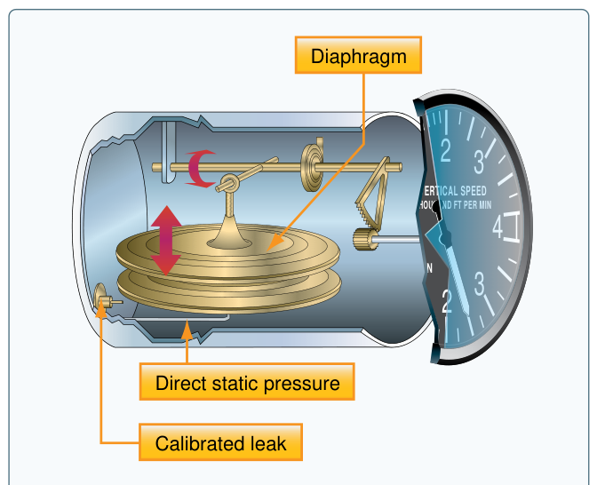
The vertical speed indicator shows how fast the airplane climbs or descends, in feet per minute. It uses the static line only, but it is still a differential pressure gauge. The static line feeds the inside of a diaphragm directly, and it feeds the case around the diaphragm through a tiny restriction called a calibrated leak.
In level flight the two pressures are equal and the needle sits on zero.
When the airplane starts to climb, the pressure inside the diaphragm drops at once, but the case pressure can only bleed down slowly through the calibrated leak. The difference moves the needle.
The faster the climb, the bigger the difference, so the needle shows the rate of climb, not the altitude.
Diaphragm (direct)
13.170 psi
Case (through the leak)
13.170 psi
Seconds since the change
0.0
Level flight. The two pressures are equal, and the needle sits on zero.
The needle takes about 6 to 9 seconds to settle on a new rate. That delay is called lag, and it is part of the design, not a fault.
FIG 10 Inside a vertical speed indicator: the diaphragm on direct static pressure and the calibrated leak into the case. Source: FAA-H-8083-25B, Figure 8-5.
Instrument Connections
Behind the panel, each line ends at a fitting on the back of an instrument. Choose the line for each fitting and check your work. Then fly the airplane and watch the three instruments together.
1234
1Airspeed indicator, fitting to the diaphragm
2Airspeed indicator, fitting to the case
3Altimeter, fitting to the case
4Vertical speed indicator, fitting to the diaphragm and the calibrated leak
Flying the Three Instruments
Climb, then level off, then descend. Watch which needles move.
Airspeed
Steady. Ram pressure minus static pressure.
Altimeter
Steady.
Vertical speed
Zero in level flight.
Level: the altimeter holds steady and the vertical speed indicator reads zero.
Optional: the same pressures on a glass display
Many newer airplanes show airspeed, altitude and vertical speed on a screen instead of round gauges. The same pitot and static lines end at a computer that turns the pressures into numbers; the EFIS and Glass Cockpit lesson covers it. Change the airspeed, start a climb, then level off.
A simplified model of a glass display: standard air and no instrument lag.
Drains, Pitot Heat and the Alternate Static Source
Water, ice and insects are what most often stop a pitot or static line from working. Each protective part on the airplane answers one of them. Turn each card over to see the part that guards against it.
Water in a static line acts like a plug that comes and goes. A slug of water at a low point can block the line in one attitude and clear in another, so the fault shows up in flight and cannot be found on the ground. If it freezes at altitude, it becomes a solid block. Drain the static system after the airplane has been out in the rain, as the maintenance manual directs.
FIG 11 The alternate static source control on the panel of an unpressurized airplane, where the alternate source is cabin air. Source: FAA-H-8083-31B, Figure 10-25.
WarningPitot heat makes the tube too hot to touch. Make sure the pitot heat switch is off and the tube has cooled before you work on it.
NEVER BLOW AIR INTO A PITOT OR STATIC LINE THAT IS CONNECTED TO THE INSTRUMENTS.
The diaphragms and capsules inside the instruments are thin, and a sudden pressure ruins them. AC 43.13-1B allows low-pressure air through a line only after the line is disconnected from the instruments. Follow the maintenance manual’s procedure.
AC 43.13-1B, Pitot/Static Systems
An Advisory Circular (AC) is a document from the Federal Aviation Administration (FAA). AC 43.13-1B gives inspection and repair methods the FAA accepts when the manufacturer’s maintenance instructions do not cover the job. Section 4 of its Chapter 12 covers pitot-static systems. Read the real text below and select each highlighted part to see what it means.
AC 43.13-1B CHG 1Chapter 12
SECTION 4. PITOT/STATIC SYSTEMS
12-51. GENERAL. In order for the pitot-static instruments to work properly, they must be connected into a system that senses the impact air pressure with minimum distortion and picks up undisturbed static air pressure.
Pitot pressure is ram air pressure picked up by a small open-ended tube about a ¼-inch in diameter that sticks directly into the air stream that produces a pressure proportional to the speed of the air movement. Static pressure is the pressure of the still air used to measure the altitude and serves as a reference in the measurement of airspeed.
Airspeed requires pitot, altimeter, rate of climb, and transponder-required static.
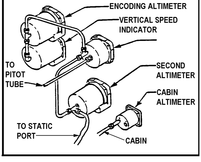
12-52. SYSTEM COMPONENTS. The conventional design of the pitot system consists of pitot-static tubes or pitot tubes with static pressure parts and vents, lines, tubing, water drains and traps, selector valves, and various pressure-actuated indicators or control units such as the altimeter, airspeed and rate-of-climb indicators, and the encoding altimeter connected to the system. (See figure 12-5.)
FIG 12 AC 43.13-1B Figure 12-5, Pitot/static system for a small aircraft.
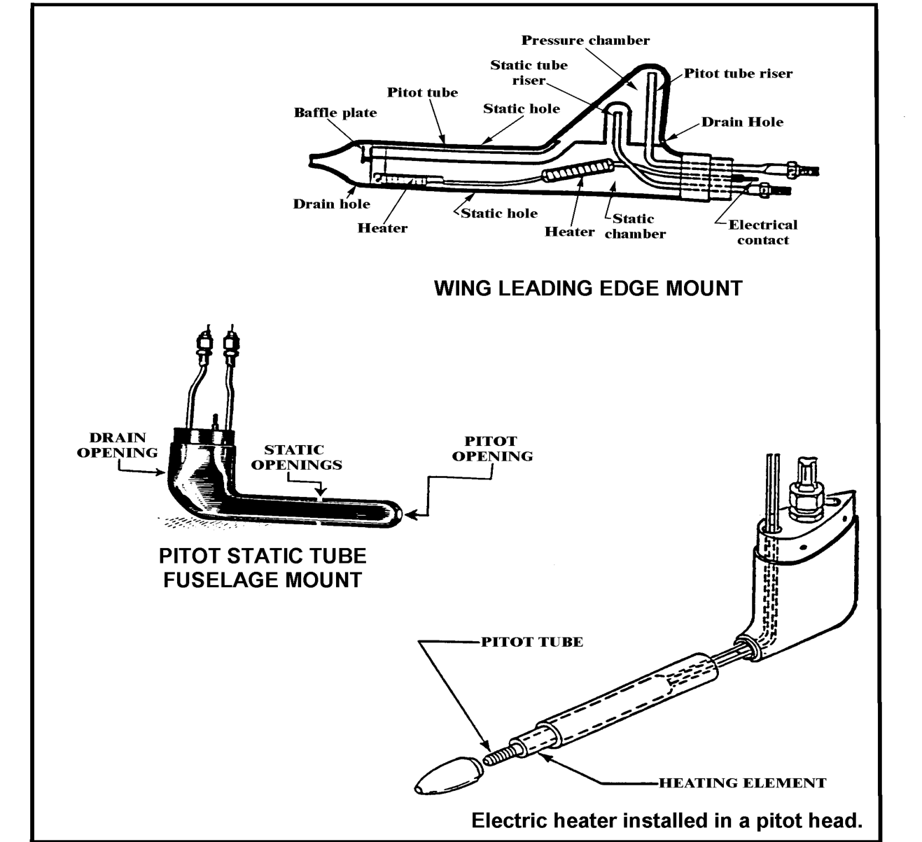
12-53. PITOT/STATIC TUBES AND LINES. The pitot tube (see figure 12-6) is installed at the leading edge of the wing of a single-engine aircraft, outside the propeller slipstream or on the fuselage of a multiengine aircraft with the axis parallel to the longitudinal axis of the aircraft, unless otherwise specified by the manufacturer.
12-54. STATIC PORTS AND VENTS (more modern trend) should be mounted flush with fuselage skin. One port is located on either side of the fuselage, usually behind the cabin.
Inspect for elevation or depression of the port or vent fitting. Such elevation or depression may cause airflow disturbances at high speeds and result in erroneous airspeed and altitude indications.
12-55. HEATER ELEMENTS. A heating element is located within the tube head to prevent the unit from becoming clogged during icing conditions experienced during flight. A switch in the cockpit controls the heater. Some pitot-static tubes have replaceable heater elements while others do not. ...
FIG 13 AC 43.13-1B Figure 12-6, Pitot/Static Tube Head.
12-56. SYSTEM INSPECTION. a. Inspect air passages in the systems for water, paint, dirt or other foreign matter. If water or obstructive material has entered the system, all drains should be cleaned. Probe the drains in the pitot tube with a fine wire to remove dirt or other obstructions. The bottom static openings act as drains for the head’s static chamber. Check these holes at regular intervals to preclude system malfunctioning.
b. Check to ensure the water drains freely. If a problem is experienced with the pitot-static system drainage or freezing at altitude, and the tubing diameter is less than 3/8-inch, replace it with larger tubing.
NOTE:It is essential that the static air system be drained after the airplane has been exposed to rain.
Source: AC 43.13-1B, Acceptable Methods, Techniques, and Practices, Aircraft Inspection and Repair, Chapter 12, Section 4, paragraphs 12-51 to 12-56, pages 12-19 and 12-20 (Change 1).
Leaks in the Lines
A leak is a crack, a loose fitting or a worn hose that lets cabin air into a line. A leak changes the pressure in the whole line, so it affects every instrument on that line. The static line feeds all three instruments; the pitot line feeds only the airspeed indicator.
Unpressurized cabin
A cabin that is not sealed and pumped up. In flight its air is a little below the outside static pressure, because of the airflow around the fuselage. On the ground, with the airplane parked, the two are the same, so a leak usually does not show until the airplane flies.
1Choose a leak.
No leak chosen yet.
2Select the instruments you predict it will affect.
All three
Static leak
The altimeter, the vertical speed indicator and the airspeed indicator.
Airspeed only
Pitot leak
The altimeter and the vertical speed indicator read normally.
Use this in both directions. If the altimeter and the vertical speed indicator are both wrong, look at the static side first: the ports, the lines and the fittings. If only the airspeed is wrong and the altitude is right, look at the pitot side. Anything that changes the pressure in the static line shows on all three instruments; blockages, such as paint over a port, are taught in Blocked Ports and Altimeter Setting.
Pitot System Leak Test
A second airplane comes in with one write-up: the airspeed reads about 10 knots low in cruise. The altimeter and the vertical speed indicator are normal. Predict which line has the leak, then check it with a pitot-static test set, a test instrument that connects to the pitot tube and the static ports and changes the pressure in the lines.
Pitot-static test set
Altitude- - -ft
Airspeed- - -kt
Hold0:00min
StaticPitot
1Prediction
Which line do you expect to leak?
2Test Set Connection
3Static System Leak Test
The field here is at 500 feet. The test set lowers the static pressure to what it is 1,000 feet above the field, holds it, and runs a 1 minute timer (shown fast).
4Pitot System Leak Test
The test set raises the pitot pressure slowly until the airspeed indicator reads 150 knots, holds it, and runs a 1 minute timer.
5Hose Inspection
Check the hoses at the bends and where they connect to the pitot mast and the airspeed indicator. Select each point.
6Hose Replacement
7Flying Configuration
These limits, 100 feet and 10 knots in 1 minute, are the AC 43.13-1B values for when the manufacturer gives none. Use the manufacturer’s values when it does. Apply and release test pressure slowly, and keep the pitot pressure equal to or higher than the static pressure; a sudden pressure or a static pressure above the pitot pressure can damage the airspeed indicator.
Source: AC 43.13-1B, paragraphs 12-57 to 12-60.
Applying the Procedure
Back to the first airplane: the altimeter reads off, the vertical speed indicator jumps, and the airspeed reads a little high. Select each step to see it on the drawing.
One loose fitting caused all three write-ups. Replacing the instruments would not have fixed it.
Check
Five questions, three answers each. Each answer tells you why it is right or wrong.
4 of 5
Needed to pass
1IdentifyIdentify the pitot tube, static ports, drains, pitot heat and alternate static source, and state the job of each.
2StateState the pressure the pitot tube senses and the pressure the static ports sense.
3NameName the pressure source for the airspeed indicator, the altimeter and the vertical speed indicator, and state what each instrument measures.
4PredictPredict which instruments a leak in the pitot line or in the static line will affect.
Question 1 of 5
0 of 5
ResultsResults
From This Lesson
01The pitot tube senses ram pressure; the static ports sense static pressure.
02Airspeed uses pitot and static. The altimeter uses static. Vertical speed uses static through a calibrated leak.
03A static leak affects all three instruments. A pitot leak affects airspeed only.
Select any row to re-read its feedback.
Field Card
1You can now name the pitot tube, static ports, drains, pitot heat and alternate static source, and say what each one does.
2You can now state that the pitot tube senses ram pressure and the static ports sense static pressure.
3You can now name the pressure source for the airspeed indicator, the altimeter and the vertical speed indicator, and what each one measures.
4You can now predict that a static leak affects all three instruments and a pitot leak affects only the airspeed indicator.
Pressures
Pitot tuberam: static plus dynamic
Static portsstatic only
Instruments
Airspeedpitot and static
Altimeterstatic
Vertical speedstatic, calibrated leak
Leaks
Static lineall three instruments
Pitot lineairspeed only
Rule
Find the line the symptoms share before you remove an instrument, and never blow air into a line that is connected to the instruments.