Panel A
Rotor
The rotor is the wheel, with its mass concentrated around its rim. Bearings, the parts that let a shaft turn with very little friction, let it spin at high speed. The line through its axle is the spin axis.
A pilot writes up two instruments after a flight: the attitude indicator and the heading indicator were slow and wandering by the end of it. The turn coordinator worked the whole time. The shop quote lists two overhauled gyro instruments.
The two instruments that wandered may share one power source, and a technician who checks that source first fixes one fault instead of replacing two good instruments.
A wheel, called a rotor, that spins at high speed inside a set of rings. While it spins it holds its position in space. Gyro is the short name, and the instruments built around one are the gyro instruments.
A pilot’s written description of a problem with the airplane, given to the shop.
Taking an instrument apart, inspecting and repairing it, and testing it to its standards before it goes back in service.
When you finish this lesson you can do the four things below. The check at the end asks about each one.
Watch the lecture. Continue appears when it ends. You can skip it for now and reopen it from this page later.
In the Pitot-Static lesson you learned that three of the six basic flight instruments read air pressure from the pitot tube and the static ports. Choose those three.
Which three instruments in the basic six run on pitot and static pressure?
The magnetic compass is a seventh instrument: a magnet floating in fluid that needs no power from the airplane and belongs to neither family. The heading indicator is set to agree with it.
Any spinning object has gyroscopic properties. A gyroscope is a wheel, or rotor, built and mounted to use them. An instrument gyro has two design features: great weight for its size, and high speed on low-friction bearings.
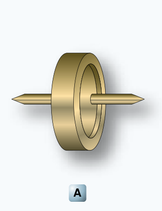
The rotor is the wheel, with its mass concentrated around its rim. Bearings, the parts that let a shaft turn with very little friction, let it spin at high speed. The line through its axle is the spin axis.
FIG 1 Gyroscopes, from a rotor alone (A) to a free gyro (D). Source: FAA-H-8083-31B, Figure 10-93.
These four features make a spinning rotor hard to move off its axis. The next page names that property.
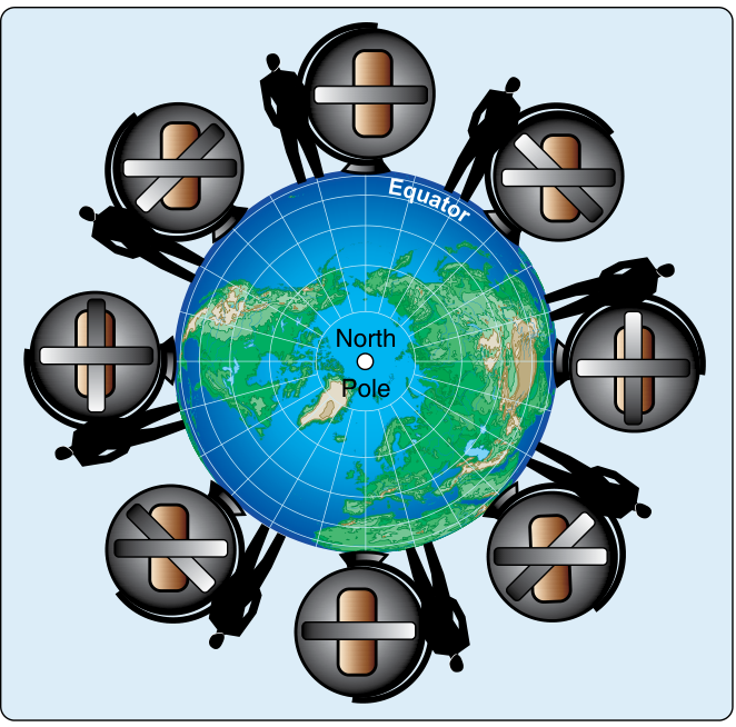
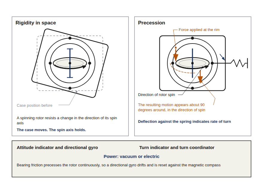
Rigidity in space is the property of a spinning rotor to stay in the plane it is spinning in, with its spin axis pointed in one direction, however its base is moved. The faster it spins, the harder it resists any change. Mounted in gimbals, the rotor holds still while the case and the airplane turn around it.
Drag to turn the view. Roll and pitch the case with the sliders. Then slow the rotor or stop it and move the case again.
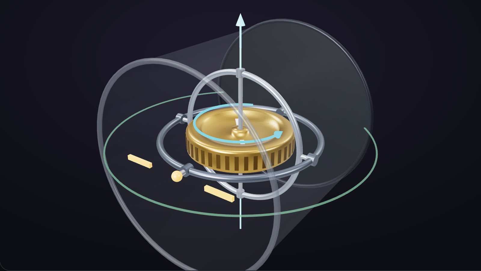
The 3D model cannot run on this device. The picture shows the same gyro, and the numbers, sliders and readout still work.
Case: level. Spin axis: 0° from vertical. The rotor is at full speed.
Select a number on the model to name the part.
Why does a gyro rotor spin at high speed?
Precession is the tilting or turning of a gyro in response to a force. The reaction does not appear at the point where the force is applied. It appears at a point 90 degrees later in the direction the rotor spins. The rate of precession goes up with the force and goes down as the rotor speed goes up.
Tap a numbered point on the rim to push it away from you. Watch where the motion appears. Then change the rotor speed or the push and try again.

The 3D model cannot run on this device. The picture shows the same gyro, and the numbers and the result still work.
Tap a numbered point on the rim to push it.
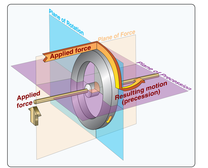
The turn indicators use precession on purpose. The heading indicator suffers from it: friction in its bearings is a small force that never stops.
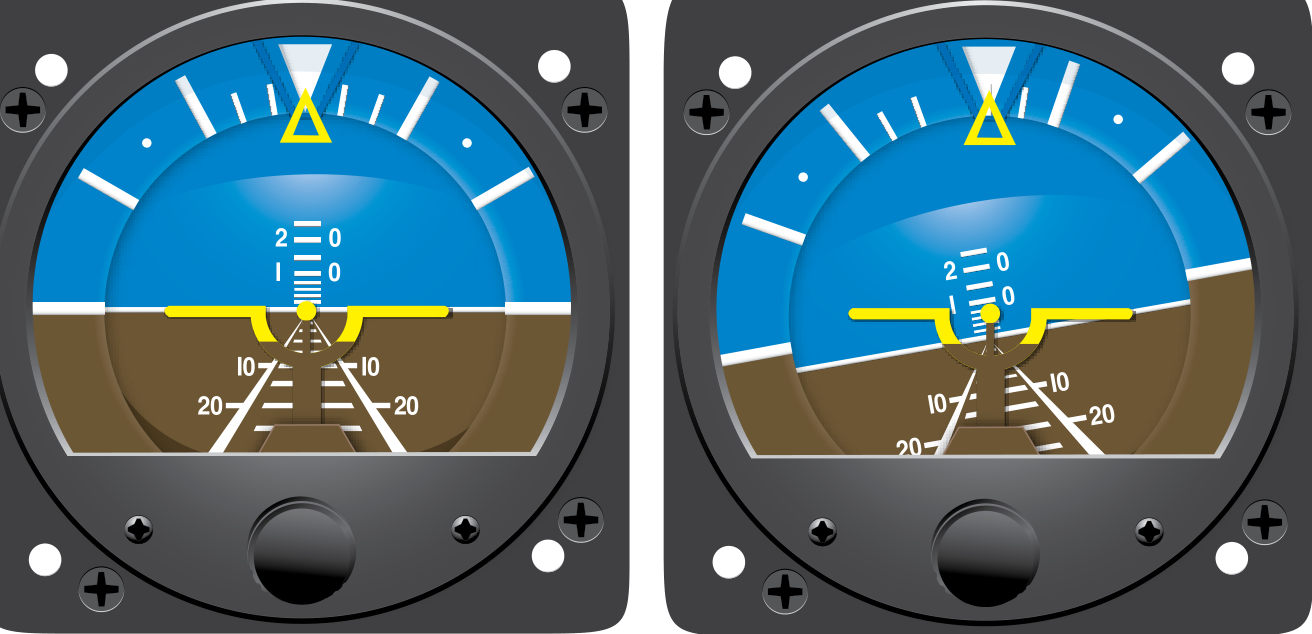
The attitude indicator shows the airplane’s attitude: its pitch, nose up or down, and its bank, wings tilted left or right, against an artificial horizon. Its gyro spins in the horizontal plane and works by rigidity in space. The horizon bar is attached to the gyro’s gimbals and stays level. The miniature airplane is fixed to the case and moves with the airplane.
Case: level. Reference: 0°. The display shows the difference between them, not a picture of the outside horizon.
An airplane rolls into a bank. What is the attitude indicator actually showing?
Many attitude indicators have limits, usually 100 to 110 degrees of bank and 60 to 70 degrees of pitch. Past a limit the gyro tumbles and gives wrong indications until it is realigned, often with a caging knob that locks the gimbals. Many modern attitude indicators do not tumble.
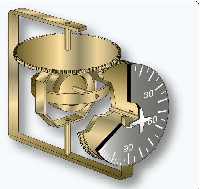
The heading indicator shows the airplane’s heading, the direction its nose points. Its rotor spins in a vertical plane, a compass card is geared to it, and rigidity holds the card steady while the airplane turns around it. It does not seek north. It is set to agree with the magnetic compass.
Two things make it drift, or creep, off its setting. Friction in its bearings precesses the rotor. And the earth turns 15 degrees every hour under a gyro that holds its place in space, so that alone can put the card off by up to 15 degrees an hour. Compare it with the magnetic compass at least every 15 minutes and reset it.
Both read 090. Fly 15 minutes and watch the heading indicator.
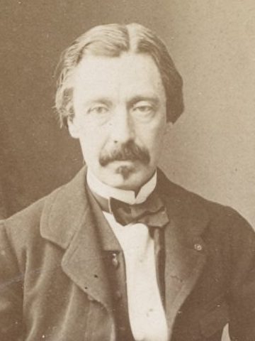
Foucault spun a heavy wheel in a set of rings to show the earth turning. He named the device a gyroscope, from Greek words for rotation and for viewing.
The wheel held its place in space while the earth, and the room, turned around it, which is what the rotor in an attitude indicator does while the airplane turns around it. Friction slowed his rotor within about 8 to 10 minutes, and the effect faded with it.
Photograph of Léon Foucault by Bertall & Cie., before 1868, public domain, via Wikimedia Commons.

On 24 September 1929, at Mitchel Field, New York, Doolittle took off, flew a set course and landed in a Consolidated NY-2 biplane with his cockpit covered, flying by instruments alone.
A Sperry Gyroscope Company artificial horizon and directional gyro gave him attitude and heading, and a Kollsman sensitive altimeter gave him altitude. They are the ancestors of the attitude indicator and the heading indicator in this lesson.
Photograph of Jimmy Doolittle, U.S. Air Force, public domain, via Wikimedia Commons.
Many airplanes now replace the attitude and heading gyros with an attitude and heading reference system (AHRS), a solid-state unit with no spinning rotor. The EFIS lesson teaches it.
Sources: IEEE Milestone, First Blind Takeoff, Flight and Landing, 1929; Smithsonian National Air and Space Museum, Sperry artificial horizon (A19711850000); “Foucault’s gyroscope,” Wikipedia; FAA-H-8083-25B, page 8-20 (AHRS).
The turn indicators use precession on purpose. Their gyro is held by a single gimbal and a spring. When the airplane yaws, which is turning about its vertical axis, the rotor precesses against the spring, and how far it moves against the spring shows the rate of turn, in degrees per second. It does not show the angle of bank.
There are 2 types: the turn-and-slip indicator and the turn coordinator. Both show the direction and rate of turn and the quality of the turn, and both back up the attitude indicator for bank information if it fails.
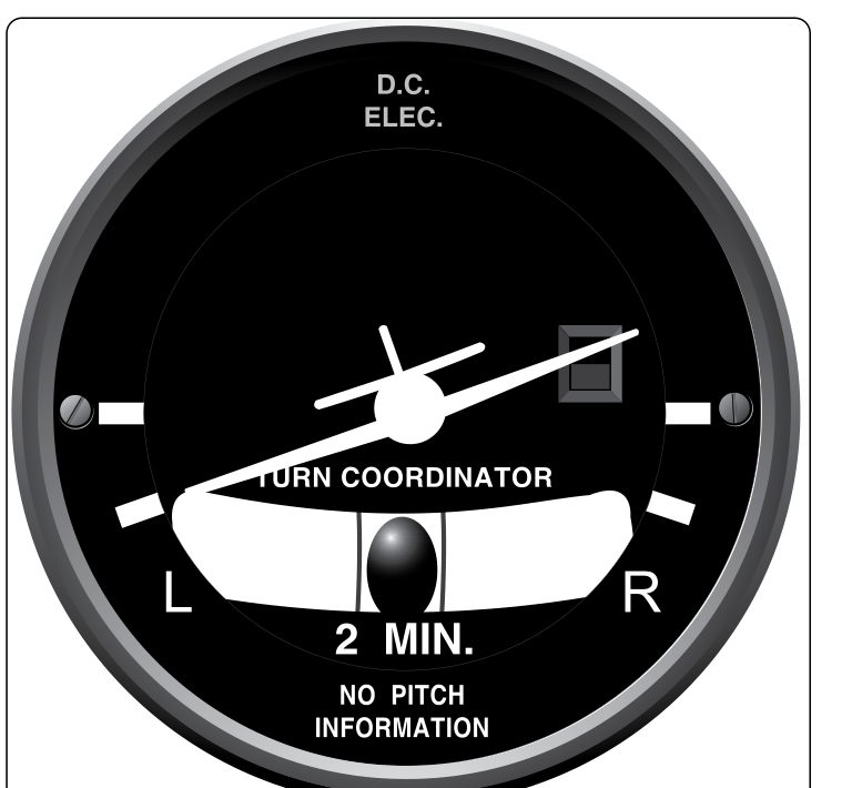
Select a number on the face to read about that part.
The turn coordinator’s gimbal is canted, tilted about 30 degrees, so its gyro senses roll as well as yaw. It shows the rate of roll first, then the rate of turn once the bank is steady.
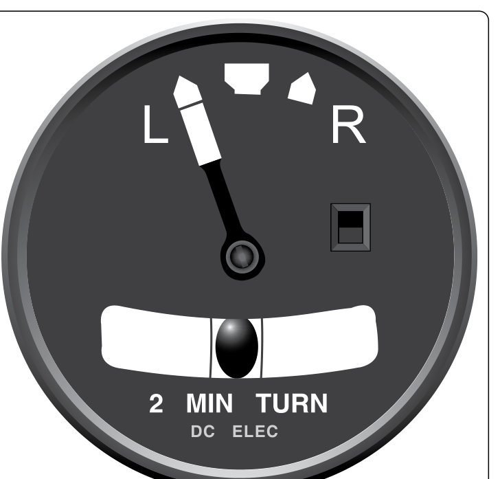
Select a number on the face to read about that part.
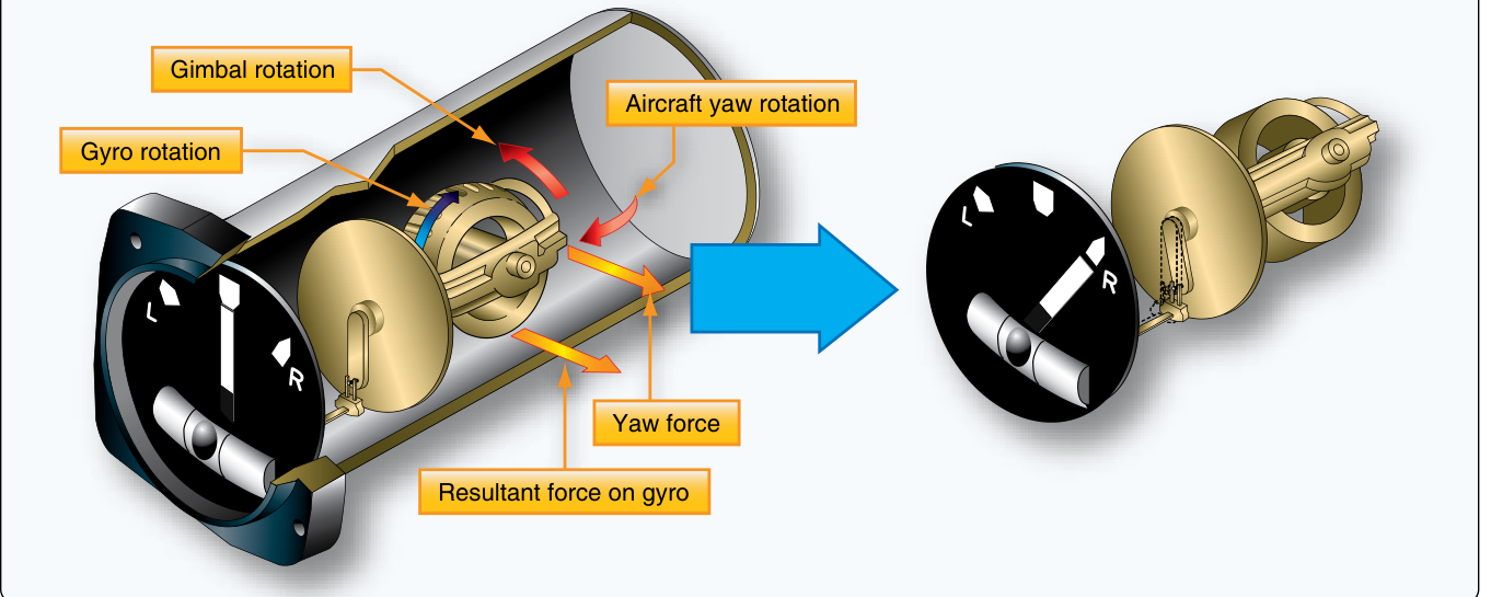
In a right turn the yaw force acts on the gyro 90 degrees around in its spin direction, so the top of the rotor tilts left against the spring. Linkage moves the needle right, the same way as the turn.
The inclinometer is the ball in the curved, liquid-filled glass tube at the bottom of a turn indicator. Gravity and the force of the turn act on it. In a coordinated turn, where the bank and the rate of turn match, the ball stays centered between the two reference lines.
The bank and the rate of turn match, and the ball stays centered between the reference lines.
A standard-rate turn is a turn of 3 degrees per second. Because a turn indicator shows a rate, you can work out how long a turn takes: divide the degrees of turn by the rate.
A full 360 degree turn at standard rate.
That is why the face says 2 MIN.
How many seconds does a 90 degree standard-rate turn take?
Fly a 90 degree right turn at standard rate, in real time, from 360 to 090.
A 4-minute turn indicator’s mark means 1.5 degrees per second. How many seconds does a full 360 degree turn take at that rate?
Every gyro needs its rotor spinning, and the power comes from one of two sources. A vacuum system pulls air through the instrument and against vanes, or buckets, cut in the rotor’s rim, the way water turns a waterwheel. An electric gyro has an electric motor whose armature, the turning part of the motor, is the rotor.
The unit of the suction gauge. Suction, or vacuum, is how far the pressure in the system is below the outside air pressure.
Select a highlighted phrase to read what it means.
In some aircraft, all the gyros are vacuum, pressure, or electrically operated. In other aircraft, vacuum or pressure systems provide the power for the heading and attitude indicators, while the electrical system provides the power for the turn coordinator. Most aircraft have at least two sources of power to ensure at least one source of bank information is available if one power source fails. The vacuum or pressure system spins the gyro by drawing a stream of air against the rotor vanes to spin the rotor at high speed, much like the operation of a waterwheel or turbine. The amount of vacuum or pressure required for instrument operation varies, but is usually between 4.5 "Hg and 5.5 "Hg.
Select a highlighted phrase.
Source: FAA-H-8083-25B, page 8-16. Text as printed.
Air drawn through the instrument
Tap the bucket where the card belongs. On a computer you can also drag the card.
A motor on the bus
Which bucket does this card belong in?
A typical vacuum system has an engine-driven vacuum pump, a relief valve, an air filter, a suction gauge and the tubing that connects them. The pump pulls air in through the filter, through the attitude and heading indicators, where it spins their rotors, and out through the pump.
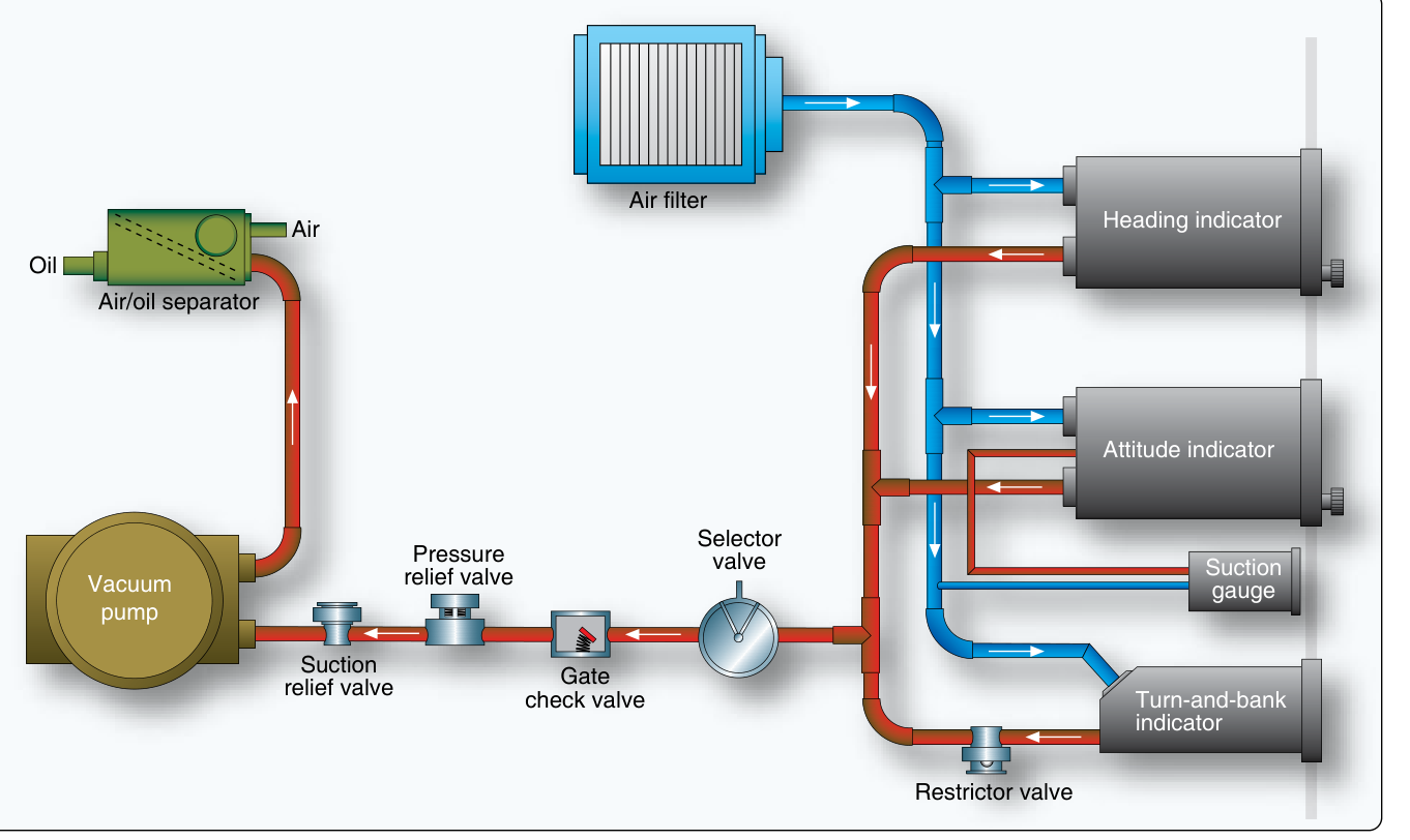
Select a part to ring it on the figure and read what it does.
The suction gauge, also called the vacuum gauge, shows how far the pressure in the instrument system is below the outside air pressure, in inches of mercury. The rotors’ speed depends on that suction, so the gauge tells you whether the vacuum gyros are spinning fast enough to be trusted.
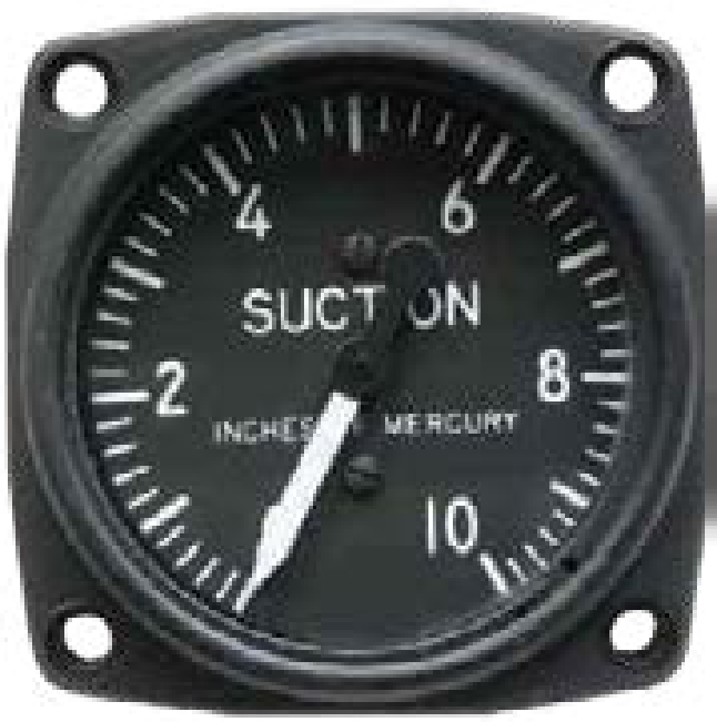
Marked by a green arc on the gauge, in a light airplane such as the Cessna 172.
The range differs by airplane and instrument. The Airframe handbook gives 3.5 to 4.5 inches for the systems it describes, and older systems ran at about 4. Read the green arc and the maintenance manual for the airplane in front of you.
Select a highlighted phrase to read what it means.
The life of an air-driven gyro instrument is determined to a great extent by the cleanliness of the air that flows over the rotor. In vacuum systems, this air is taken from the cabin where there is usually a good deal of dust and very often tobacco smoke. Unless all of the solid contaminants are removed from the air before it enters the instrument, they will accumulate, usually in the rotor bearings, and slow the rotor. This causes an inaccurate indication of the instrument and will definitely shorten its service life. Dry air pumps are also subject to damage from ingested contaminants, and all of the filters in the system must be replaced on the schedule recommended by the aircraft manufacturer, and more often if the aircraft is operated under particularly dusty conditions, especially if the occupants of the aircraft regularly smoke while flying.
Select a highlighted phrase.
Source: AC 43.13-1B CHG 1, paragraph 12-38, page 12-17. Text as printed. Range: FAA-H-8083-25B, page 8-16; FAA-H-8083-31B, page 10-45; Cessna Model 172 Maintenance Manual, 37-10-00.
At cruise power the suction gauge reads 3.0 inches of mercury, and its green arc runs from 4.5 to 5.5. What does the reading tell you?
Gyros fail by power source. A symptom that hits every instrument on one source points at that source, not at each instrument on it. Predict first, then fail the source and watch the panel.
Step 1. Tap each instrument you expect to go bad when the vacuum pump fails. Then fail the vacuum pump.
Everything is working. The suction is inside the green arc.
Back to the write-up: the attitude indicator and the heading indicator were slow and wandering, and the turn coordinator worked. Trace it from the power source.
Select a step to see it on the panel.
Five questions, three answers each. Each answer tells you why it is right or wrong.
Properties
Instruments
Power
A symptom that hits every instrument on one power source points at that source. Read the suction gauge before you pull a gyro.
Sources: FAA-H-8083-25B, Chapter 8; FAA-H-8083-31B, Chapter 10; FAA-H-8083-15B, Chapter 5; AC 43.13-1B, paragraph 12-38.