An airplane comes back from the paint shop with masking tape still over both static ports. After its first flight the pilot writes up the altimeter and the vertical speed indicator (VSI): “Altimeter and VSI inoperative. Airspeed acting strange in the climb.” A technician replaces the altimeter, and the next flight brings back the same write-up.
FIG 1 A static port on the side of the fuselage, still covered with masking tape after paint.
A blocked port lights no warning and trips no circuit breaker, so you find it only by reading the pattern of wrong indications.
Aircraft write-upDiscrepancy and corrective action
1
DiscrepancyAltimeter and VSI inoperative. Airspeed acting strange in the climb.
Corrective actionReplaced altimeter.
2
Discrepancy RepeatAltimeter and VSI inoperative. Airspeed acting strange in the climb.
Corrective actionOpen
Static port
A small flush hole in the side of the fuselage that lets the pressure of the still outside air into the static line, the tubing that carries it to the instruments.
Vertical speed indicator (VSI)
The instrument that shows how fast the airplane climbs or descends, in feet per minute.
Write-up
A pilot’s written report of a problem with the airplane. The technician answers it with the corrective action, the work that fixed it.
Learning Objectives
When you finish this lesson you can do the four things below. The check at the end asks about each of them.
1PredictPredict the airspeed indicator in a climb and a descent with the pitot tube blocked, with its drain hole blocked and with it open.
2PredictPredict the altimeter, the VSI and the airspeed indicator in a climb and a descent with the static system blocked.
3NameName the blockage from a set of indications, and state the small shifts an alternate static source causes.
4SetSet the altimeter to the right reference, the local setting below 18,000 feet above mean sea level (MSL) and 29.92 inches of mercury at and above, and work the altitude error of a wrong setting.
Key Facts
Blocked Pitot
Drain hole blocked: the airspeed rises in a climb and falls in a descent. Drain hole open: the airspeed drops to zero.
Blocked Static
The altimeter freezes, the VSI reads zero, and the airspeed reads low in a climb and high in a descent.
Alternate Static
Cabin air brings the instruments back, with the altimeter and the airspeed reading slightly high.
Altimeter Setting
Local setting below 18,000 feet MSL, 29.92 at and above. One inch of mercury is about 1,000 feet.
Lecture Video
Watch the lecture. Continue appears when it ends. You can skip it for now and come back to this page later.
The Pitot-Static Lines
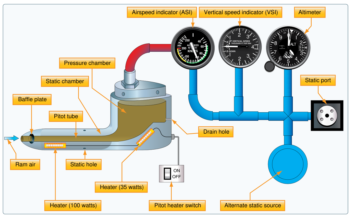
In the pitot-static lesson you traced the lines from the pitot tube and the static ports to the three instruments. Every blockage in this lesson is worked from those lines.
FIG 2 The pitot-static system: the pitot tube feeds only the airspeed indicator, and the static port feeds all three instruments. Source: FAA-H-8083-25B, Figure 8-1.
From the pitot-static lesson
Which instruments are connected to the static line?
Ram
Pitot tube
Ram pressure is the outside air pressure plus the pressure made by the airplane’s motion through the air.
Static
Static ports
Static pressure is the outside air pressure alone.
Climb
Outside air
Outside air pressure falls as the airplane climbs and rises as it descends.
Every answer in this lesson comes from these three facts, with one line closed.
Pitot side
The Blocked Pitot Tube
When ice or debris closes the pitot tube’s opening and its drain hole at the same time, the ram pressure in the pitot line is trapped. The airspeed indicator then rises in a climb and falls in a descent, whatever the airplane’s real speed.
Diaphragm
A thin, sealed metal capsule inside the airspeed indicator. The pitot line fills it with ram pressure, the static line fills the case around it, and the needle shows how far it swells.
Trapped pressure
Pressure held in a line when its openings are closed. It cannot change, whatever the airplane does.
Ice closes the pitot tube and its drain hole at 4,000 feet while the airplane flies at 110 knots. A knot is one nautical mile per hour. The airplane keeps flying at 110 knots. Move the airplane up and down.
Altitude4,000 ft
Real airspeed110 knots
Airspeed indicator110 knots
At the moment of blockage the reading is still right: 110 knots.
FIG 3 The airspeed indicator and what is inside it. The pitot line (amber) is trapped at its 4,000 foot pressure; the case (cyan) follows the outside air.
Level off and the needle stops wherever it is. A change in power or in real speed does not move it, because no new ram air reaches the diaphragm. The needle now follows altitude, not speed: the airspeed indicator acts like an altimeter.
A pilot who climbs while holding that rising number is slowing toward a stall, the point where the wing no longer holds the airplane up.
Pitot side
The Pitot Tube Drain Hole
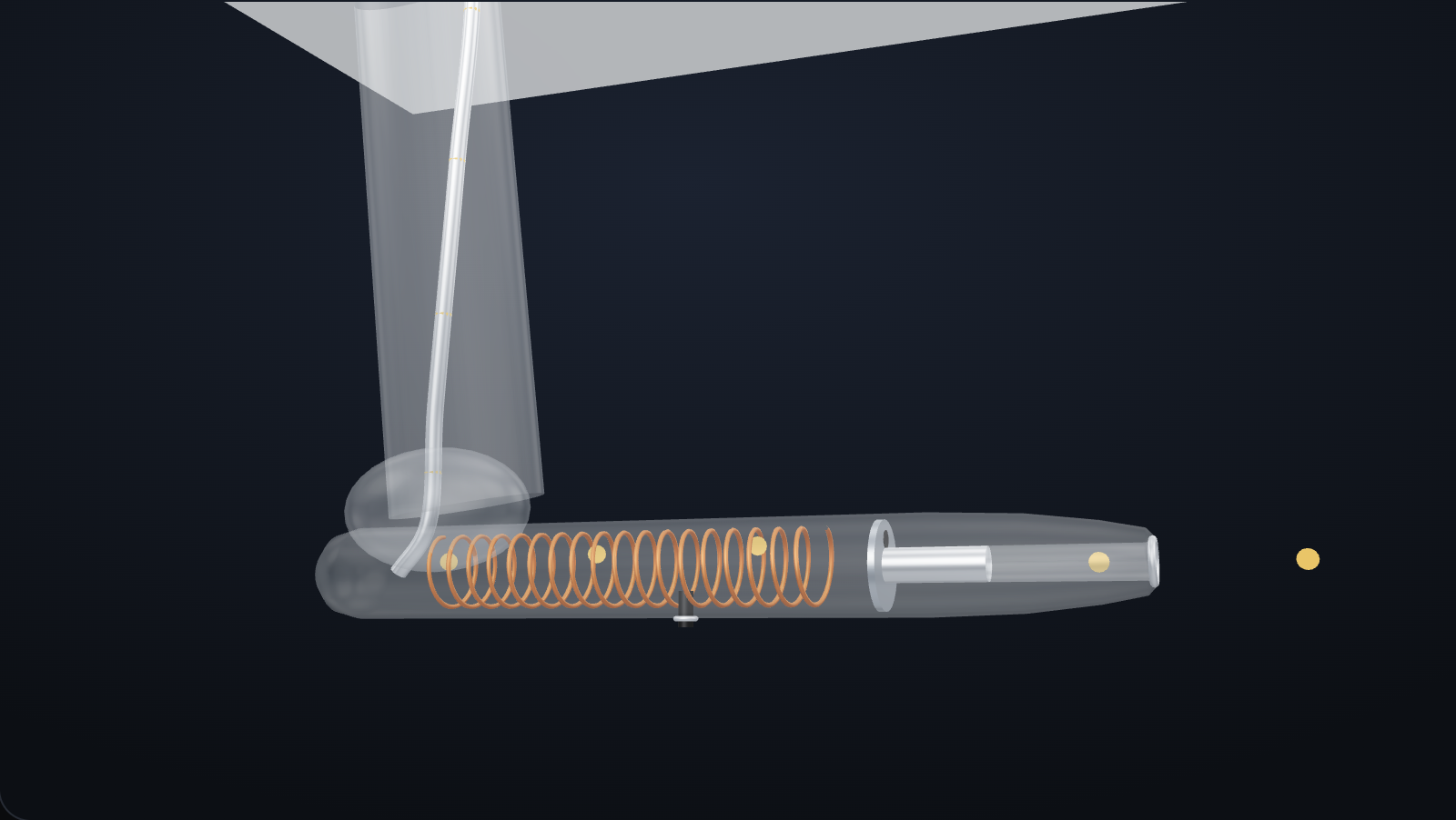
The drain hole is a small hole at the low point of the pitot tube that lets rain water run out. If the opening is blocked and the drain hole stays open, the air in the pitot line leaks out through the drain until it is at outside pressure. The airspeed indicator then falls to zero, even in level flight at normal speed.
Drag to turn the model. Tap a number to name the part. Use the buttons to block the opening and the drain hole.
Ram airBlocked
110 kt
The 3D model cannot run on this device. The picture shows the same tube, and the numbers and buttons work on it.
FIG 4 A pitot tube on its mast below the wing, with its skin drawn see-through. Dots show the air in the tube and the pitot line.
Opening
Drain hole
Normal. Ram air fills the pitot line, and water that gets in runs out of the drain hole. The airspeed indicator shows 110 knots.
Select a number on the model to name the part.
On the airplane, the opening gets blocked by insects such as the mud dauber wasp, which builds mud nests in small holes, by a pitot cover left on, and by ice when the airplane flies in visible moisture without pitot heat. The Pilot's Handbook of Aeronautical Knowledge (PHAK), the handbook for pilots from the Federal Aviation Administration (FAA), says both openings of the pitot tube must be checked before flight, and a cover keeps insects out while the airplane sits.
Caution. Clear a blocked pitot tube as the aircraft maintenance manual directs. Do not drive a drill bit or a stiff wire into the opening, which pushes the debris deeper, and never blow compressed air through the line toward the instruments, which can damage them: disconnect the line at the instruments first. AC 43.13-1B, the FAA’s advisory circular of acceptable inspection and repair methods, allows a fine wire to probe the drain holes clean.
Static side
The Blocked Static System
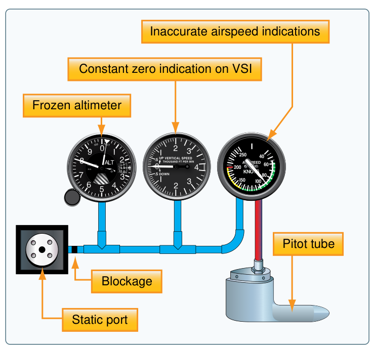
When the static ports or the static line are blocked, the static pressure in the line is trapped at its value at the moment of blockage. One blockage changes all three instruments.
Select a number on the handbook’s drawing to see what each instrument does.
FIG 5 A blocked static system. Source: FAA-H-8083-25B, Figure 8-11.
Select a number on the drawing.
Two frozen static instruments next to a moving airspeed needle is the picture of a blocked static system.
Static side
Airspeed with the Static System Blocked
With the static line blocked, the airspeed indicator’s case holds the trapped static pressure while the pitot line keeps changing with altitude. The airspeed reads low above the blockage altitude and high below it.
Climb
Outside pressure falls, so ram pressure falls with it, while the case holds the higher trapped pressure. The difference is too small, and the airspeed reads low.
Descent
Outside pressure rises, so ram pressure rises, while the case holds the lower trapped pressure. The difference is too large, and the airspeed reads high.
The static line blocks at 8,500 feet while the airplane cruises at 120 knots. It keeps flying at 120 knots. Choose what the airspeed indicator shows at each altitude, then select Check.
Climbed to 9,000 feet
Pitot line
Case, trapped
About 76 knots: low.
Level at 8,500 feet
Pitot line
Case, trapped
120 knots: right at the blockage altitude.
Descended to 8,000 feet
Pitot line
Case, trapped
About 152 knots: high.
The airspeed reads right only at the blockage altitude. The farther the airplane goes from it, up or down, the larger the error. At this speed, 500 feet is enough for an error of 30 to 45 knots.
FAA-H-8083-25B, pages 8-10 and 8-11
The FAA Handbook on Blockage
The Pilot’s Handbook of Aeronautical Knowledge (PHAK) is the FAA’s handbook for pilots, and it covers the same blockages. Read its words below and select each number to see what that part means on the airplane.
Blocked Pitot System
The pitot system can become blocked completely or only partially if the pitot tube drain hole remains open. If the pitot tube becomes blocked and its associated drain hole remains clear, ram air is no longer able to enter the pitot system. Air already in the system vents through the drain hole, and the remaining pressure drops to ambient (outside) air pressure. Under these circumstances, the ASI reading decreases to zero because the ASI senses no difference between ram and static air pressure.
If both the pitot tube opening and the drain hole should become clogged simultaneously, then the pressure in the pitot tube is trapped. No change is noted on the airspeed indication should the airspeed increase or decrease. If the static port is unblocked and the aircraft should change altitude, then a change is noted on the ASI. The change is not related to a change in airspeed but a change in static pressure.
The pitot tube may become blocked during flight due to visible moisture. Some aircraft may be equipped with pitot heat for flight in visible moisture. Consult the AFM/POH for specific procedures regarding the use of pitot heat.
Blocked Static System
If the static system becomes blocked but the pitot tube remains clear, the ASI continues to operate; however, it is inaccurate. The airspeed indicates lower than the actual airspeed when the aircraft is operated above the altitude where the static ports became blocked because the trapped static pressure is higher than normal for that altitude. When operating at a lower altitude, a faster than actual airspeed is displayed due to the relatively low static pressure trapped in the system.
A blockage of the static system also affects the altimeter and VSI. Trapped static pressure causes the altimeter to freeze at the altitude where the blockage occurred. In the case of the VSI, a blocked static system produces a continuous zero indication.
Some aircraft are equipped with an alternate static source in the flight deck. In the case of a blocked static source, opening the alternate static source introduces static pressure from the flight deck into the system. Flight deck static pressure is lower than outside static pressure. Check the aircraft AOM/POH for airspeed corrections when utilizing alternate static pressure.
Select a number in the handbook text.
Source: FAA-H-8083-25B, Pilot’s Handbook of Aeronautical Knowledge, Chapter 8, pages 8-10 and 8-11. Quoted as printed.
Static side
The Alternate Static Source
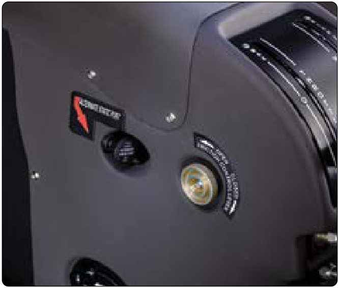
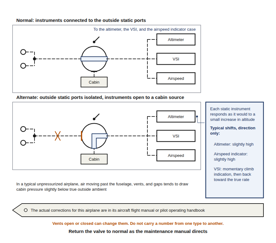
Most airplanes with a pitot-static system have an alternate static source, a valve the pilot opens when the static ports are blocked. In an unpressurized airplane, one whose cabin is not sealed and pumped up to a higher pressure, it takes static pressure from inside the cabin. The instruments work again, with small errors in a known direction.
FIG 6 On an unpressurized airplane, the alternate source of static air is the cabin. Source: FAA-H-8083-31B, Figure 10-25.
Level flight at 3,000 feet and 120 knots.
3,000 ft
Altimeter
Reads the real altitude.
120 kt
Airspeed
Reads the real airspeed.
0 ft/min
VSI
Zero in level flight.
Air flowing around the fuselage makes the cabin pressure a little lower than outside. Lower static pressure looks to each instrument like a little more altitude.
The numbers in this example come from a cabin 0.03 inches of mercury below outside pressure. The real corrections for each airplane are in its Airplane Flight Manual (AFM) or Pilot’s Operating Handbook (POH), and opening a cabin vent can change them. Do not carry a number from one airplane type to another. A pressurized airplane cannot use cabin air, so its alternate static source is a second set of ports on the outside of the fuselage.
FIG 7 The alternate static valve. Normal: the instruments connect to the outside static ports. Alternate: the outside ports are shut off and the instruments open to the cabin.
Caution. After troubleshooting, return the alternate static valve to normal as the maintenance manual directs. An airplane released with the alternate source selected flies with an altitude error the next crew does not know about.
Troubleshooting
From Indications to Blockage
A pilot’s write-up gives you the indications, and you work back to the blockage. Start with the altimeter and the VSI, because they use static pressure alone.
Look at the altimeter and the VSI first.
Did the altimeter freeze and the VSI stay on zero while the airplane climbed or descended?
Static side blocked
Confirm with the airspeed: low in a climb, high in a descent. In flight the pilot opens the alternate static source; on the ground, inspect the static ports and the static line.
The static side is clear, so the fault is on the pitot side, where the airspeed indicator is the only instrument. What did the airspeed do?
Pitot tube and drain hole both blocked
The airspeed indicator is following altitude.
The pitot line is not holding ram pressure
The opening is blocked with the drain hole open, or the line leaks. Check the tube, the drain hole and the line.
FIG 8 From the indications to the blockage, altimeter and VSI first.
Partial restriction
A blockage that narrows a line without sealing it. Pressure still gets through, but late, so the instrument lags: in a fast descent the altimeter reads high, then catches up after the airplane levels off.
Pitot Side or Static Side
Pitot side
The pitot tube, its drain hole and the pitot line
Tap the side where the card belongs. On a computer you can also drag the card.
Static side
The static ports and the static line
Which side does this card belong to?
Altimeter setting
The Kollsman Window
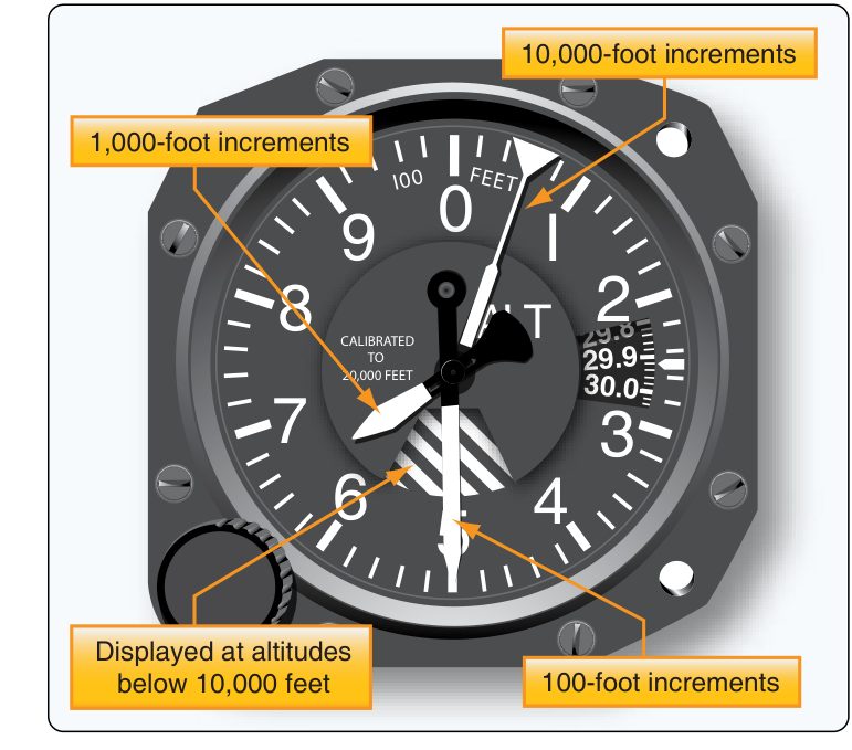
The Kollsman window is the small window on the altimeter face that shows the barometric setting, in inches of mercury. You change it with the knob. The setting tells the altimeter what air pressure to treat as sea level. It does not change the airplane’s height, and it does not fix a faulty altimeter.
Inches of mercury (in Hg)
A unit of air pressure: how many inches up a glass tube the air pushes a column of mercury. Standard sea level pressure is 29.92 in Hg.
Altimeter setting
The air pressure a weather station reports, corrected to sea level. It changes with the weather and from place to place, so the pilot updates it during the flight.
Today’s altimeter setting is 30.12. The airplane flies at 3,000 feet MSL. Turn the knob and watch where the altimeter puts sea level.
Window29.92
Altimeter reads2,800 ft
Real height3,000 ft MSL
The window is 0.20 in Hg below today’s setting, so the altimeter reads about 200 feet low.
FIG 9 The altimeter and a side view, to scale. Drag the knob round, use the buttons, or select the knob and press the arrow keys.
Wind it up
Higher setting
A higher setting tells the altimeter that sea level pressure is higher, so the same outside pressure means more height. The reading goes up.
Wind it down
Lower setting
A lower setting makes the reading go down.
The altimeter is a pressure gauge with a scale in feet. The pressure at a given height changes with the weather, so the same height gives a different pressure on different days. The setting tells the altimeter which sea level pressure to measure from.
Paul Kollsman and the Sensitive Altimeter
FIG 10 A sensitive altimeter with three pointers and its Kollsman window, showing 29.9. Source: FAA-H-8083-31B, Figure 10-32.
1928
Paul Kollsman, instrument maker
In 1928 Paul Kollsman invented a way to adjust an altimeter for the day’s air pressure. That made the sensitive altimeter possible: the FAA’s name for an altimeter that shows height in feet above a pressure level you select.
The next year, on 24 September 1929, Jimmy Doolittle took off, flew a set course and landed at Mitchel Field, New York, with a hood over his cockpit so he could not see outside. He flew on instruments alone, and one of them was a Kollsman sensitive altimeter.
Every barometric window you set today still carries Kollsman’s name.
Sources: FAA-H-8083-31B, Airframe Handbook, page 10-19. FAA-H-8083-15B, Instrument Flying Handbook, page 5-3. The date and place: IEEE Milestone, First Blind Takeoff, Flight and Landing, 1929.
Altimeter setting
Altimeter Settings in 14 CFR 91.121
Title 14 of the Code of Federal Regulations (14 CFR), the rules of the Federal Aviation Administration (FAA), says what goes in the window. Section 91.121 is printed below. Select each number to read what that part means.
§ 91.121 Altimeter settings.
(a) Each person operating an aircraft shall maintain the cruising altitude or flight level of that aircraft, as the case may be, by reference to an altimeter that is set, when operating:
(1) Below 18,000 feet MSL, to:
(i) The current reported altimeter setting of a station along the route and within 100 nautical miles of the aircraft;
(ii) If there is no station within the area prescribed in paragraph (a)(1)(i) of this section, the current reported altimeter setting of an appropriate available station; or
(iii) In the case of an aircraft not equipped with a radio, the elevation of the departure airport or an appropriate altimeter setting available before departure; or
(2) At or above 18,000 feet MSL, to 29.92″ Hg.
(b) The lowest usable flight level is determined by the atmospheric pressure in the area of operation as shown in the following table:
Current altimeter setting
Lowest usable flight level
29.92 (or higher)
180
29.91 through 29.42
185
29.41 through 28.92
190
28.91 through 28.42
195
28.41 through 27.92
200
27.91 through 27.42
205
27.41 through 26.92
210
Paragraph (c), which converts minimum altitudes to flight levels, is not shown.
Select a number in the regulation.
Source: 14 CFR 91.121, Altimeter settings, as printed by the Government Publishing Office. The dashes after “operating” and “to” are shown as colons.
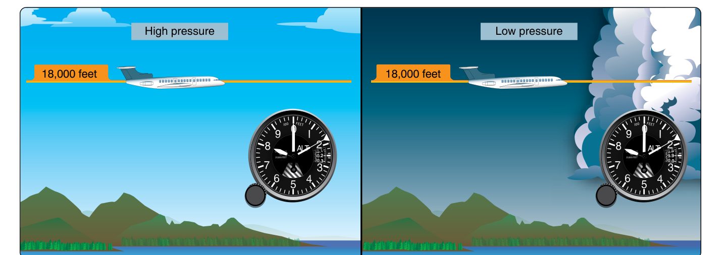
FIG 11 Above 18,000 feet MSL every aircraft sets 29.92, and the altimeter reads pressure altitude. In high or low pressure the true altitude is above or below what is shown. Source: FAA-H-8083-31B, Figure 10-35.
Altimeter setting
The Altimeter Ground Check
To check an altimeter on the ground, set the current reported altimeter setting in the window and compare the reading with the field elevation, the published height of the airport above mean sea level. The FAA’s Instrument Flying Handbook says a reading more than 75 feet from field elevation makes the altimeter questionable, and it goes to a repair station, a shop the FAA certificates to repair instruments, for evaluation.
Field elevation620 ft
FIG 12 The customer’s altimeter on the ramp with 30.04 in the window. It reads 780 feet.
On the ramp
You are checking a customer's altimeter on a field with an elevation of 620 feet. You set the current reported setting, 30.04, and the altimeter reads 780 feet. What do you do?
Turning the knob until the reading looks right hides the fault you were sent to find. You moved the reference. You did not repair anything.
The ramp can sit a little higher or lower than the published field elevation, so the handbook says to check again at the run-up area before you call an error of more than 75 feet.
Source: FAA-H-8083-15B, Instrument Flying Handbook, pages 5-5 and 5-37.
Altimeter setting
Altimeter Setting Error
When the window holds the wrong setting, the altimeter is off by about 1,000 feet for every inch of mercury of difference. The rule comes from the Pilot’s Handbook of Aeronautical Knowledge, and you can work any setting error with it.
1 in Hg of setting error is about 1,000 feet of altitude error.
A pilot flies from Mineral Wells, Texas, where the setting was 29.94, to Abilene, where it is 29.69, and does not update the window. Abilene’s field elevation is 1,791 feet. The pilot flies the traffic pattern at 2,600 feet on the altimeter, planning to be about 800 feet above the ground.
FIG 13 The Abilene traffic pattern, heights to scale. Select each step.
The handbook’s memory aid: “Going from a high to a low, look out below.”
Flying from high pressure into low pressure without resetting the window puts the airplane lower than it reads.
Source: FAA-H-8083-25B, Pilot’s Handbook of Aeronautical Knowledge, pages 8-4 to 8-6.
Altimeter setting
Setting Error Practice
Work each one the same way: find the difference, multiply by 1,000 feet, then decide the direction. A window higher than the real setting makes the altimeter read high. A window lower than the real setting makes it read low.
1Difference
2Times 1,000 feet
3Direction
Problem 1
The window still holds 30.15 from the departure airport. The current setting where you are flying is 29.85. The altimeter reads 3,000 feet. About how high is the airplane?
Problem 2
The window is set to 29.82. The current setting is 30.02. The altimeter reads 1,500 feet. About how high is the airplane?
Hands-on
The Three-Instrument Panel
This panel has a working airspeed indicator, altimeter and VSI on one pitot line and one static line. Pick a fault, predict what each instrument does in a climb, then fly the climb and compare. The last case is a ground check with the knob.
1Pick a case
2Predict each instrument
3Fly the climb and compare
Airspeed
Altimeter
VSI
The airplane is on a field 1,250 feet above sea level. The current reported setting is 30.12, and the window shows 29.92. Turn the knob until the altimeter reads field elevation.
Airspeed
120 knots
Altimeter
4,500 ft
VSI
0 ft/min
The airplane, really
Altitude
4,500 ft
Airspeed
120 knots
Flight
Level
Pick a case to start.
Cases done: 0 of 5.
Applying the Procedure
Back to the airplane from the paint shop. The altimeter and the VSI did not work, the airspeed acted strangely in the climb, and a new altimeter did not fix it. Work the write-up with these steps.
1Read the write-up. Two instruments failed together, and both are static instruments.
2Look at the altimeter and the VSI first. Both stopped in a climb, which points to the static side.
3Confirm with the airspeed. It read low in the climb, which is what live ram pressure against trapped static pressure does.
4Do not replace another instrument. Nothing failed: the new altimeter did exactly what the old one did.
5Walk around the airplane and look at the static ports. Both are covered with masking tape from the paint shop.
6Remove the tape and its adhesive as the maintenance manual directs. Do not push anything into the holes or blow air into the ports or the line.
7Inspect the ports and the static line as the maintenance manual directs, and check that the alternate static valve is set to normal.
8The altimeter change opened the static system. A static system that has been opened must pass a leak test before the airplane flies under instrument flight rules (IFR), flying by the instruments in weather. The Certification Checks lesson covers that test.
9Release the airplane only after a walkaround shows the pitot tube and both static ports open, and record the work.
Step 1 of 9
Aircraft write-upDiscrepancy and corrective action
1
DiscrepancyAltimeter and VSI inoperative. Airspeed acting strange in the climb.
Corrective actionReplaced altimeter.
2
Discrepancy RepeatAltimeter and VSI inoperative. Airspeed acting strange in the climb.
Corrective actionOpen
Warning. Never leave a static port taped, plugged or covered after paint, wash or maintenance without a bright flag that can be seen from outside the airplane, and never release an airplane without a walkaround that checks every pitot and static opening. A taped static port cannot be seen from the cockpit, and taped ports have caused fatal accidents. AC 43.13-1B, paragraph 12-57b, says the same after a leak test: remove the tape from the static ports and the pitot drain holes.
Check
Five questions, three answers each. Each answer tells you why it is right or wrong.
4 of 5
Needed to pass
1PredictThe airspeed indicator with a blocked pitot tube, drain hole blocked or open.
2PredictAll three instruments with a blocked static system.
3NameThe blockage from the indications, and the alternate static shifts.
4SetThe right altimeter reference, and the error of a wrong one.
Question 1 of 5
0 of 5
ResultsResults
Select any row to re-read its feedback.
Field Card
1You can now predict the airspeed indicator with a blocked pitot tube, with the drain hole blocked or open.
2You can now predict all three instruments with a blocked static system.
3You can now work from the indications back to the blockage, altimeter and VSI first, and name the shifts the alternate static source causes.
4You can now set the right altimeter reference and work the error of a wrong one: one inch of mercury is about 1,000 feet.
Blocked Pitot
Drain blockedRises in a climb, falls in a descent.
Drain openFalls to zero.
Altimeter and VSINormal.
Blocked Static
AltimeterFrozen at the blockage altitude.
VSIZero.
AirspeedLow climbing, high descending.
Alternate Static
AltimeterSlightly high.
AirspeedSlightly high.
VSIShort climb, then normal.
CorrectionsIn the AFM or POH.
Altimeter Setting
Below 18,000 ft MSLCurrent local setting.
At and above29.92.
Error1 in Hg is about 1,000 feet.
Ground checkWithin 75 feet of field elevation.
Rule
Look at the altimeter and the VSI first. Never turn the knob to hide an altimeter error, and never release an airplane without checking every pitot and static opening.