States
Logic 1high, true
Logic 0low, false
Gapa fault, not a state
Levelsfrom the maintenance data
The pilot of an airplane with retractable landing gear reports that the gear warning horn sounds on every approach when the power is pulled back, even with three green gear lights showing. The last shop replaced the gear warning unit, the box that decides when to sound the horn. The horn still sounds.
The warning unit is built from logic. If you can read its logic, you can tell whether the box is bad or one of its inputs is wrong before another box is bought.
A horn in the cockpit that sounds when the throttle is retarded (pulled back) and the landing gear is not down and locked.
Circuits that work with only two conditions, on or off, and decide an output from their inputs.
When the horn sounds: FAA-H-8083-31B, pages 10-74 and 13-23.
When you finish this lesson you can do the four things below. The check at the end asks about each of them.
A circuit with one output whose state is set by its inputs, by a fixed rule.
A table that lists the output for every possible combination of inputs.
In the Transistors and Inverters lesson you used a transistor as a switch. No base current turned it fully off, called cutoff. Enough base current turned it fully on, called saturation. Logic gates are built from transistors used exactly this way. Answer from memory.
In a switching circuit, how many useful states does the transistor have?
Source: FAA-H-8083-31B, page 11-25.
Digital logic recognizes exactly two states. There is no third state and nothing in between. One state is called Logic 1 and the other Logic 0. In a circuit the two states are two voltages: usually voltage present for Logic 1 and no voltage for Logic 0. Manufacturers write different words for the same two states.
Select a marked passage, or select Next, to read what it means.
There are two conditions that may exist, 1 or 0. In a digital circuit, these are equivalent to voltage or no voltage. Within the binary system, these two conditions are called Logic 1 and Logic 0. Using just these two conditions, gates can be constructed to manipulate information.
Select a marked passage in the text, or select Next.
Put each name with the state it means. Drag the card, or tap a bucket. Positive logic means the more positive voltage is Logic 1.
The high state
Tap the bucket where the card belongs. On a computer you can also drag the card.
The low state
Which bucket does this card belong in?
Sources: FAA-H-8083-31B, page 11-25; FAA-H-8083-30B, page 12-120.
A logic state is a band of voltage, not one exact voltage. A logic family, a group of logic circuits built to the same electrical rules, defines a range that counts as low and a separate range that counts as high, with a deliberate gap between them. A working signal passes through the gap only while it switches. A receiver that sees a voltage parked in the gap has no defined state.
0.35 VLow, Logic 0
FIG 1 The low band, the gap and the high band of one example logic family. These band limits are an example from equipment data, not numbers to memorize.
Below 0.8 V is low. Above 2.0 V is high. You read 0.35 V, 4.6 V and 1.4 V on three inputs. What does the 1.4 V reading mean?
An AND gate has two or more inputs and one output. Its output is high only when every input is high. If any input is low, the output is low. An AND gate works like switches in series with a lamp: the lamp lights only when every switch is closed.
| A | B | Output | Tried |
|---|---|---|---|
| 0 | 0 | 0 | |
| 0 | 1 | 0 | |
| 1 | 0 | 0 | |
| 1 | 1 | 1 |
Try all four combinations of the two switches. 0 of 4 tried.
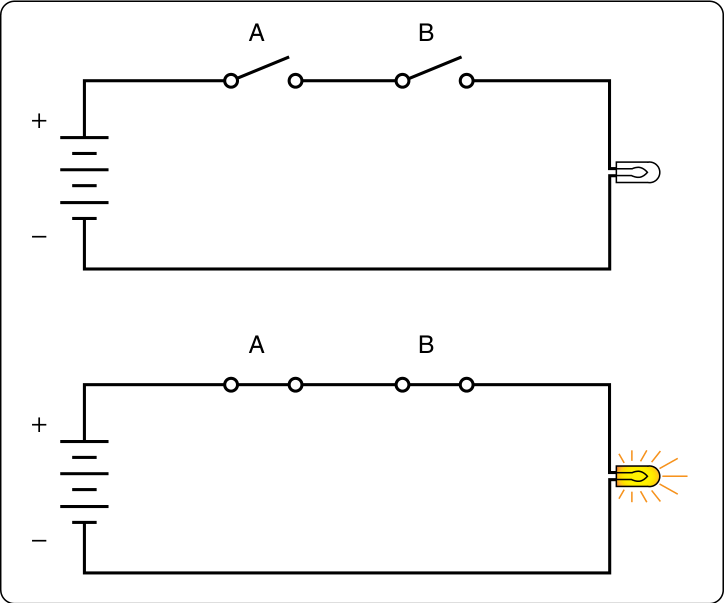
Source: FAA-H-8083-30B, page 12-121.
An OR gate has two or more inputs and one output. Its output is high when any one input is high. The output is low only when every input is low. An OR gate works like switches in parallel with a lamp: closing any one switch lights the lamp. An annunciator, a labeled warning light on the panel, is often driven this way.
Select a marked passage, or select Next, to read what it means.
The OR Gate
The example used is a “DOOR UNSAFE” annunciator. Let’s say in this case that the plane has one cabin door and a baggage door. In order for the annunciator light on the master warning panel to extinguish, both doors must be closed and locked. If any one of the doors is not secured properly, the baggage door OR the cabin door, then the “DOOR UNSAFE” annunciator illuminates. In this case, two switches are in parallel with each other. If either one of the two switches is closed, the light bulb lights up. The lamp is off only when both switches are open.
Select a marked passage in the text, or select Next.
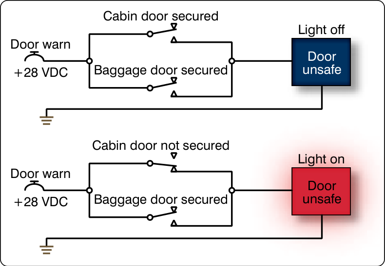
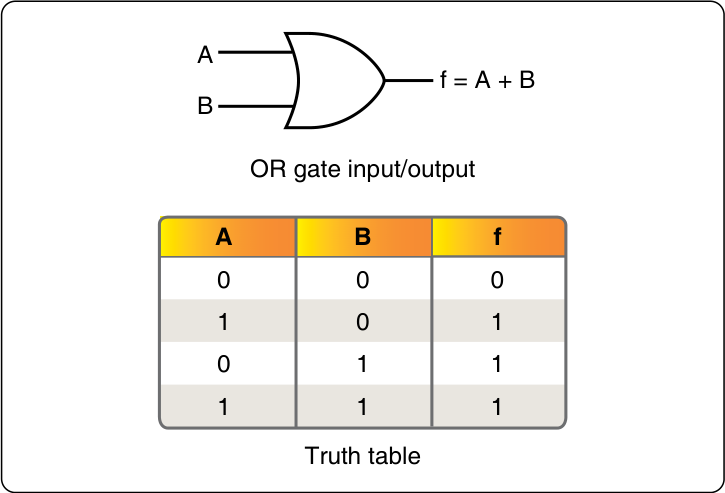
Which circuit lights the DOOR UNSAFE light?
A NOT gate, also called an inverter, has one input and one output. Its output is always the opposite of its input: high in gives low out, and low in gives high out. Its symbol is a triangle with a small circle, called a bubble, on the output. The bubble is the important part: wherever a bubble sits on a gate symbol, it means inversion at that point.
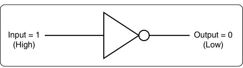
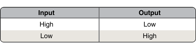
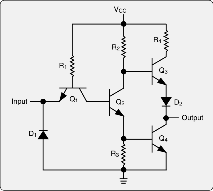
Select a card to turn it over.
A signal whose active condition is the low level: the wire sits high and is pulled low when the condition occurs. A NOT gate turns it around for logic that needs a high.
Sources: FAA-H-8083-30B, page 12-121; FAA-H-8083-31B, pages 11-25 to 11-27.
Two switches, A and B, feed an AND gate and an OR gate at the same time. A also feeds a NOT gate. Predict the three outputs for each setting, then check.
Setting 1 of 4
A = 1, B = 0
Pick 0 or 1 for each gate, then select Check. The switches below move to the setting.
A truth table lists the output for every possible combination of inputs, one combination per row. Nothing is left to memory. To build one, list every on and off combination of the inputs, with no combination twice, then work out the output for each row. Miss a row and you have missed a condition the airplane can be in.
A = cabin door not secured. B = baggage door not secured. Light = DOOR UNSAFE on. Each is 1 or 0.
Select a cell to change it between 0 and 1. Fill the A and B columns with all four combinations, then the Light column. Then select Check.
| A | B | Light |
|---|---|---|
Sources: FAA-H-8083-31B, page 11-25; FAA-H-8083-30B, page 12-122.
On many high-performance aircraft, a proximity sensor reports each gear’s position. A proximity sensor senses a metal part, called the target, near its face without touching it. It returns one voltage to the gear logic when its target is near and another when the target is far, and those two voltages are Logic 0 and Logic 1.
Select a number on the figure to read about that part.
Swipe the figure sideways to see all of it.
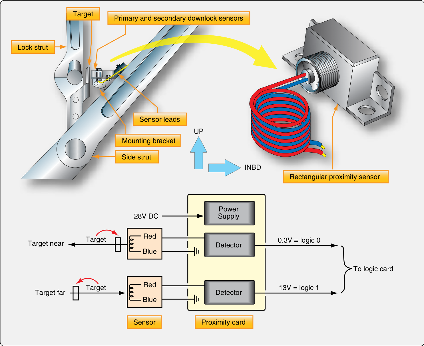
Each number marks one part of the figure.
Select a marked passage, or select Next, to read what it means.
Landing Gear Safety Devices
The use of proximity sensors for gear position safety switches is common in high-performance aircraft. An electromagnetic sensor returns a different voltage to a gear logic unit depending on the proximity of a conductive target to the switch. No physical contact is made. When the gear is in the designed position, the metallic target is close to the inductor in the sensor which reduces the return voltage. This type of sensing is especially useful in the landing gear environment where switches with moving parts can become contaminated with dirt and moisture from runways and taxi ways. The technician is required to ensure that sensor targets are installed the correct distance away from the sensor.
Select a marked passage in the text, or select Next.
The logic card reads 13 V from a downlock sensor. What does the card see?
Logic levels on an airplane are not one number. This sensor uses 0.3 V and 13 V, the autopilot inputs on the next page use 28 V, and circuit cards often use 5 V or less. The maintenance data gives the levels for the equipment in front of you.
An AND gate decides when a set of conditions are all met at the same time. The autopilot is a good example: it must not engage, or take control, unless every part it needs reports valid. Valid means the part has power and has checked itself as working.
Select a number on the figure to read about that part.
Swipe the figure sideways to see all of it.
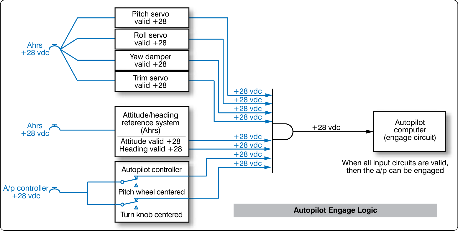
Each number marks one part of the figure.
Select a marked passage, or select Next, to read what it means.
The AND Gate
An example of AND logic could possibly be engage logic found in an autopilot. In this case, the autopilot would not be allowed to be engaged unless certain conditions are first met. Such conditions could be: Vertical gyro is valid AND directional gyro is valid AND all autopilot control knobs are in detents AND servo circuits are operational. Only when these conditions are met does the autopilot engage.
Select a marked passage in the text, or select Next.
The turn knob is not centered, so its input reads 0 V. Every other input reads +28 V. Can the autopilot engage?
Each job below is done by one of the three gates. A master caution light, a single light that tells the pilot to look at the annunciator panel, is one of them: it lights when any one of the conditions it watches is present.
Read each card and put it with the gate that does the job. Drag the card, or tap a bucket.
Every input high
Tap the bucket where the card belongs. On a computer you can also drag the card.
Any input high
The opposite
Which bucket does this card belong in?
In many light airplanes the gear warning logic is built from switches, not from a circuit card. A limit switch is a spring-loaded switch that a gear part presses when the gear reaches the end of its travel. Each gear has an up-limit and a down-limit switch. A throttle switch closes when the throttle is pulled back below a set point. The horn sounds when the throttle is retarded and a gear is not down.
Select a marked passage, or select Next, to read what it means.
A throttle switch is also used in conjunction with landing gear circuits on most aircraft. If the throttle is retarded (closed) beyond a certain point, the aircraft descends and eventually lands. Therefore, many manufacturers activate a throttle switch whenever engine power is reduced. If engine power is reduced too low, a warning horn sounds telling the pilot to lower the landing gear. Of course, this horn need not sound if the gear is already DOWN or the pilot has selected the DOWN position on the gear switch. This same horn also sounds if the aircraft is on the ground, and the gear handle is moved to the UP position.
Select a marked passage in the text, or select Next.
Select a number on the figure to read about that part.
Swipe the figure sideways to see all of it.
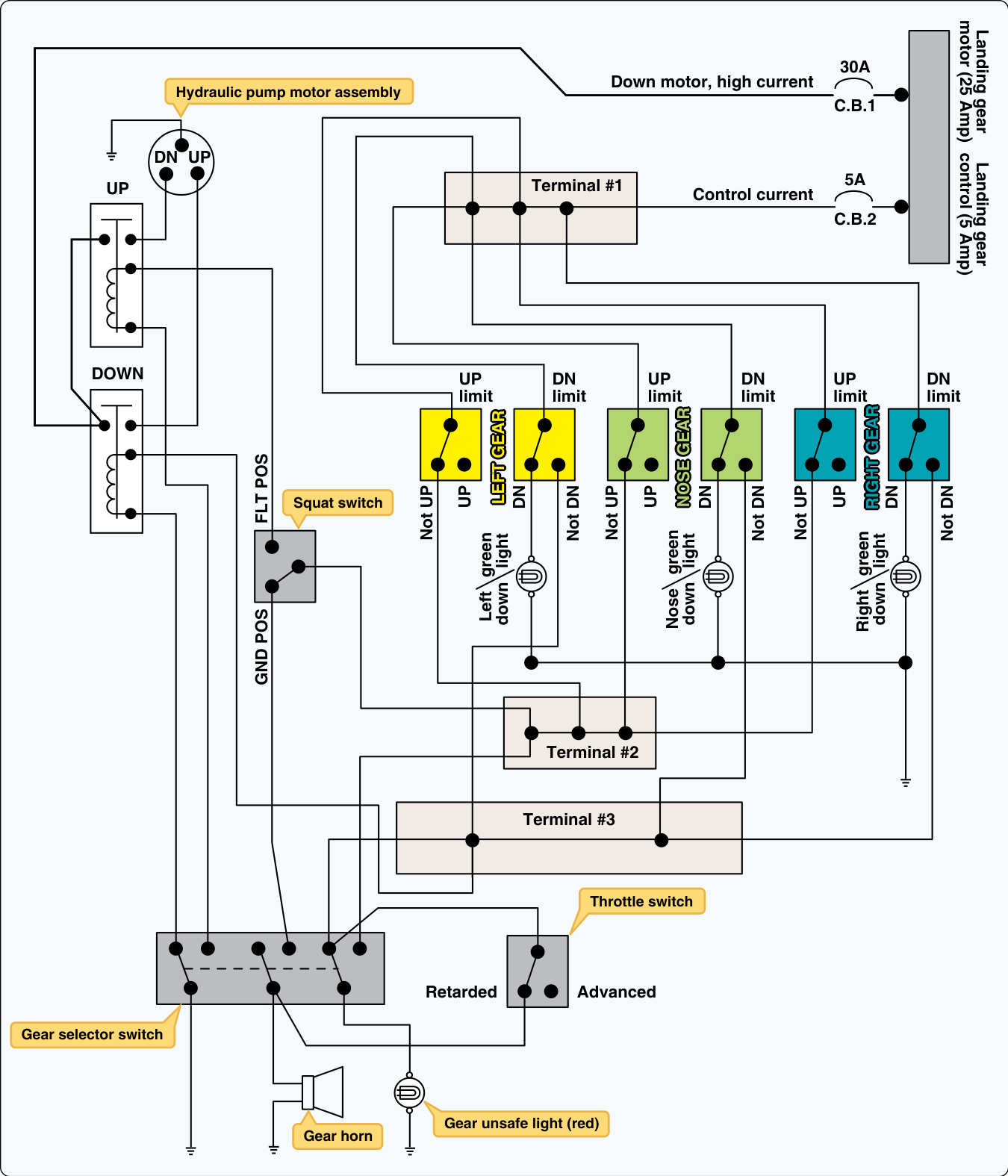
Each number marks one part of the figure.
Sources: FAA-H-8083-31B, pages 9-51 to 9-53.
The gear-down input to the warning logic often comes from a micro switch, a small switch that needs only a short push on its plunger to change over. It has three terminals: common (C), normally open (NO) and normally closed (NC). When the gear locks down, a part of the gear presses the switch’s lever, the plunger moves, and common connects to NO. Rigging is setting a part’s position so it works at the right point; a switch out of rig does not change over.
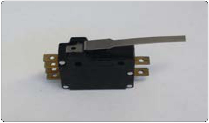
Each number marks one part. Then set the gear to Down and locked, and try Out of rig.
“A limit switch is simply a spring-loaded, momentary contact switch that is activated when a gear reaches its limit of travel.”
FAA-H-8083-31B, page 9-51.
Sources: FAA-H-8083-31B, pages 9-51 and 9-98, and the Glossary (microswitch). In this example common gets 28 V and NO feeds the warning unit.
Each input can be 0 or 1, so each input you add doubles the number of combinations. The number of rows in a truth table is 2 multiplied by itself once for each input, written 2 to the power of the number of inputs.
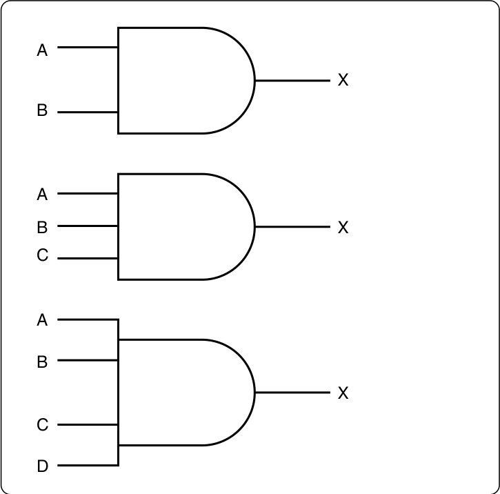
Worked example. How many rows does the truth table for the three-input AND gate need?
Your turn. The autopilot engage AND gate in FIG 9 has 8 inputs. How many rows does its truth table have?
On a logic diagram, the gear warning is a NOT gate feeding an AND gate. The gear-down signal is high when the gear is down and locked. The NOT gate turns it into gear-not-down. The AND gate sounds the horn only when gear-not-down and throttle-retarded are both high. Predict first, then set the switches to check.
Gear retracted. Throttle at cruise power. Does the horn sound?
| Gear down | Throttle retarded | NOT gear down | Horn |
|---|---|---|---|
| 1 | 0 | 0 | 0 |
| 1 | 1 | 0 | 0 |
| 0 | 0 | 1 | 0 |
| 0 | 1 | 1 | 1 |
Back to the horn that sounds with three green lights, after the warning unit was already replaced. Work it with these steps. Select a step to see what you find; at step 4, measure at each test point on the drawing.
What you find
The gear-down input reads low with the gear locked, and the AND output is high. Which is it?
Five questions, three answers each. Each answer tells you why it is right or wrong.
You can now:
States
Gates
Tables
Troubleshooting
Sources: FAA-H-8083-30B, pages 12-120 to 12-125; FAA-H-8083-31B, pages 9-51 to 9-53, 9-98, 11-25, 11-26, 13-22 and 13-23. The gear warning case is a training case.