Path
Pathsone
Currentthe same at every point
Two readings differlook for a second path
The flight crew reports a dim landing light. You install a new lamp and check that the circuit breaker has not opened. With the light on, you measure 28 V at the bus but only 22.3 V across the lamp.
Measured at the bus with the light on.
Measured across the new lamp. It is 5.7 V less than the bus.
The lamp shares one path with the circuit breaker, the switch, a connector, the wiring and the ground, so the other 5.7 V is being dropped across one of those parts. This lesson shows you how to find which part, by knowing what each part should drop.
A metal bar that is the common point where electrical power is shared out to the circuits. The circuit breakers take their power from it.
A switch that opens by itself when the current is too high, to protect the wire. A fuse does the same job by melting open, and it must be replaced. A circuit breaker can be reset by hand, but only after the fault that tripped it has been found and fixed.
When you finish this lesson you can do the four things below. The check at the end asks about each of them.
The same current flows through every part of the circuit.
Add the resistances to get the total, then divide the source voltage by the total to get the current.
Each drop is the current times that part's resistance, and the drops add up to the source voltage.
A break in the path, called an open, stops the current everywhere. Added resistance lowers the current and changes every drop.
Watch the lecture. Continue appears when it ends. You can skip it for now and reopen it from this page later. The lecture is 5:18 long.
In the Ohm's Law lesson, you worked with one load, the part that does the work, on one source. This lesson uses the same law on circuits with more than one load. The question below uses a single load.
A 9 V source is connected across a single 20 ohm load. What current flows?
Series circuits have only one path for current to flow. Start at the source, trace through each part in turn, and you come back to the source without reaching a branch, a point where the path splits into two or more paths.
A circuit with only one path for current. The parts are connected end to end, so the same current flows through each one.
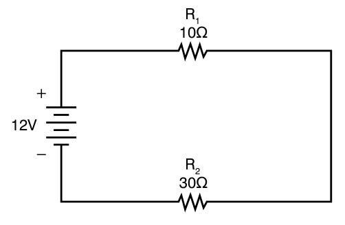
The path goes from the source, through R1, through R2 and back to the source. There is one path and no branch, so this is a series circuit.
Which drawing shows a series circuit?
There is only one path, so every electron that leaves the source passes through every part on its way back. The current is the same at every point in a series circuit.
Total current (It) equals the current through the first part (I1), which equals the current through the second part (I2), and so on for every part.
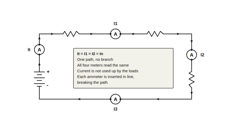
All four ammeters read 0.50 A. The current is the same at every point.
A lamp changes electrical energy into light and heat. The electrons pass through it and continue around the loop, so an ammeter after the lamp reads the same current as one before it.
A 28 V bus feeds a lamp through a circuit breaker, a switch and a wire. An ammeter between the circuit breaker and the switch reads 2.4 A. What does an ammeter in the return wire, after the lamp, read?
In a series circuit, resistance adds up. Each part adds its own opposition to the same current, one part after another, so the total resistance is the sum of every resistance in the path.
The circuit starts with 10, 20 and 30 ohm resistors, 60 ohms in total. Add or remove a resistor and watch the total resistance change.
The total resistance goes down, and the current goes up.
The gap is a break in the path, called an open, and the current stops.
Every part of an aircraft circuit adds to this sum: the wire, each splice (a joint that connects two wires), each connector (a plug and socket that let the wiring be taken apart), the switch and the ground terminal (the fitting that connects a ground wire to the aircraft structure). A clean, tight connection adds almost nothing, and a corroded or loose one adds more. The corroded terminal lug in the Resistance lesson, a metal fitting squeezed onto the end of a wire so it can be bolted in place, added 0.90 ohm.
A voltage drop is the voltage across one part while current flows through it. It is the share of the source's pressure used to push the current through that part. In a series circuit, the voltage drops add up to the source voltage.
This is Kirchhoff's voltage law, which you learned in the Voltage lesson: the sum of the voltage drops around a closed loop equals the source voltage.
Volts above the source's negative side
2.77 + 2.08 + 4.15 = 9.00 V
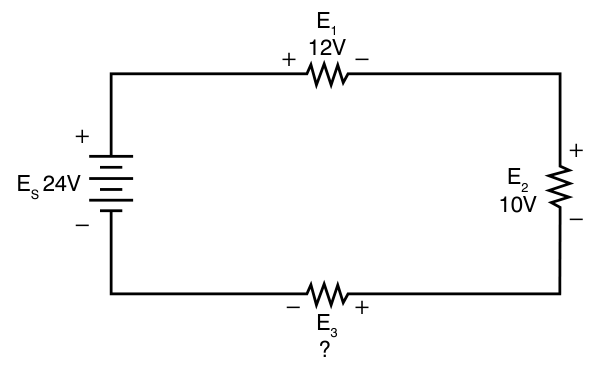
In this circuit the source is 24 V, and two of the drops are 12 V and 10 V. What is the third drop, E3?
An open is a break in the path, such as a burned-out lamp filament (the thin wire inside the lamp that glows) or a wire that has come loose. An open has infinite resistance, so no current flows through it. A series circuit has only one path, so one open stops the current everywhere, and every load goes dead at the same moment.
This is why aircraft loads that must keep working when another load fails are never wired in series with each other. Some older holiday light strings were wired in series, and one burned-out bulb darkened the whole string. If the aircraft lights were wired in series, a failed landing light would also turn off the navigation lights, the red, green and white position lights on the wingtips and tail. The Parallel Circuits lesson shows how aircraft loads are wired instead.
Four lamps are wired in series, and one filament opens. What happens to the other three?
You can find an open with a voltmeter while the circuit is powered.
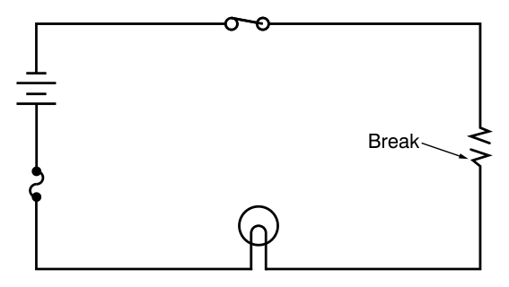
The resistor has burned open. With the switch on, the lamp still does not light, because the only path is broken.
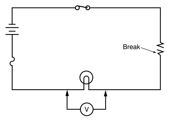
Put the voltmeter across the lamp. It reads 0 V. No current flows, so the lamp drops no voltage, and a reading of 0 V tells you the lamp is not the open.
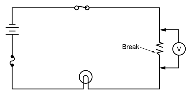
Put the voltmeter across the open resistor. It reads the battery voltage. The good parts drop 0 V, and the drops still add up to the source, so the whole source voltage appears across the open.
FIG 8 An open circuit, a voltmeter across the lamp, and a voltmeter across the open resistor. Adapted from FAA-H-8083-30B, Figures 12-174 to 12-176 (switch redrawn closed).
Three lamps are wired in series on a 28 V supply, and all three are dark. With the power on, you read 0 V across lamp 1, 0 V across lamp 2 and 28 V across lamp 3. Which lamp is open?
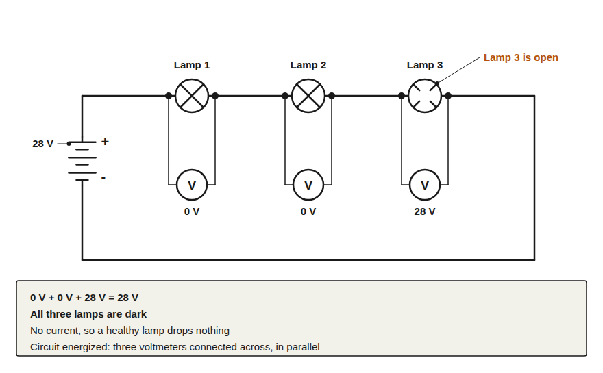
When resistance is added to a series circuit, the total resistance goes up and the current goes down. Current has an indirect relationship with resistance: when one goes up, the other goes down.
The circuit as drawn: 12 V across 10 + 30 ohms.
When the total resistance doubles, the current falls to half.
When the total resistance is cut in half, the current doubles.
Source: FAA-H-8083-30B, Series DC Circuits, pages 12-34 and 12-35, the circuit in Figure 12-82.
Each card is a change to a series circuit. Sort it by what the change does to the current in the one path.
Total resistance falls.
Tap the bucket where the card belongs. On a computer you can also drag the card.
Total resistance rises, and current still flows.
The path is open, with infinite resistance.
Which bucket does this card belong in?
On the aircraft, the landing light is wired in series with the other parts of its circuit. From the bus, the current has one path: through a circuit breaker, the feed wire, the switch, a connector, the lamp, a ground wire and a ground terminal on the structure, and back to the battery through the structure.
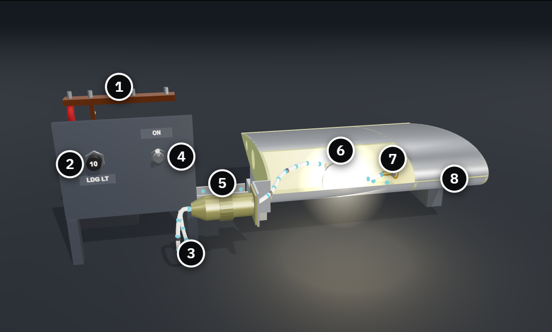
Loading the 3D circuit.
Drag to turn the circuit. Select a numbered part to read what it does, then choose a condition.
The wiring and connections of a circuit, from the bus out to the load and from the load back to its ground on the structure, always drop a little of the voltage. For that reason, a load never gets the full bus voltage. The Federal Aviation Administration (FAA) sets a limit for how much the wiring and connections may drop.
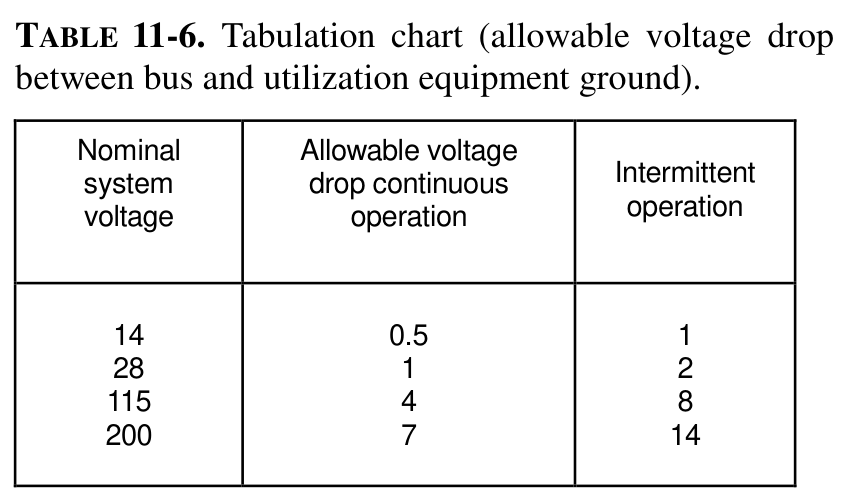
| System voltage | Continuous operation | Intermittent operation |
|---|---|---|
| 14 | 0.5 | 1 |
| 28 | 1 | 2 |
| 115 | 4 | 8 |
| 200 | 7 | 14 |
A guidance document the FAA publishes. AC 43.13-1B gives methods the FAA accepts for inspection and repair, and it is used when the aircraft manufacturer gives no instructions for the job. Here AC means advisory circular, not alternating current.
A load that can stay on for more than two minutes at a time, such as a radio.
A load that runs for no more than two minutes at a time, such as the motors that move the landing gear or the flaps.
A limit set by the aircraft or equipment manufacturer comes first. To check a circuit, AC 43.13-1B says to measure the voltage drop across it: if the drop is within the limit, the resistance of the circuit is acceptable.
The wiring and connections of a lamp circuit on a 28 V system drop 1.68 V. What does Table 11-6 tell you?
To find the current in a series circuit, find the total resistance first. Then use Ohm's Law on the whole circuit: the total current is the source voltage divided by the total resistance.
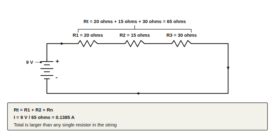
When you work this by hand, 9 divided by 65 is often cut short to 0.13 A. That is close, but carry all the digits through the problem and round only at the end, because cutting the current short makes the drops on the next page add up to less than the source.
Resistors of 12, 33 and 47 ohms are wired in series across a 9 V source. What current flows?
Each part's voltage drop is the circuit current times that part's resistance. The current is the same through every part, so the largest resistance takes the largest drop.
Ex is the drop across any one part, and Rx is that part's resistance.
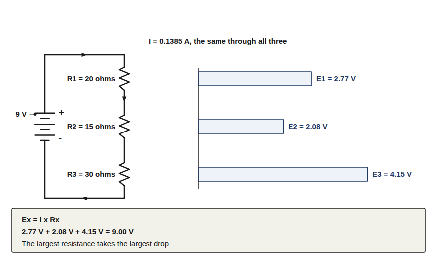
2.77 + 2.08 + 4.15 = 9.00 V
2.60 + 1.95 + 3.90 = 8.45 V
The drops add up to 8.45 V, close to 9 V, only because the current was cut short to 0.13 A before multiplying. Carry all the digits and round only at the end, and the drops add up to the 9 V source.
Resistor values and currents are often written with a prefix. Change each value to ohms and amperes before you multiply.
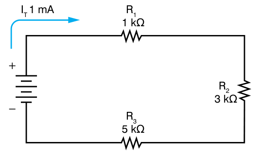
One thousand. 3 kΩ is 3 × 1,000 = 3,000 ohms.
One thousandth. 1 mA is 1 / 1,000 = 0.001 A.
The current in this circuit is 1 mA. What is the voltage drop across R2, the 3 kΩ resistor?
Now work the landing light circuit. On a 28 V bus, the lamp is 7.84 ohms when it is lit and hot. When the circuit is in good condition, the wiring, circuit breaker, switch, connector and ground together add 0.25 ohm in series with it. By itself on 28 V, this 100 W lamp would draw 3.57 A. The wiring and connections in series with it make the current a little lower.
A loose connector pin raises the wiring and connections from 0.25 ohm to 1.50 ohms. What voltage does the lamp get?
Corrosion at the ground terminal adds 1.75 ohms to the one path, so the wiring and connections rise from 0.25 ohm to 2.00 ohms. Predict what that does, then check the numbers.
Predict each change.
The current
The voltage across the lamp
The voltage across the wiring and connections
| Value | Normal | Corroded ground terminal |
|---|---|---|
| Wiring and connections | 0.25 ohm | 2.00 ohms |
| Total resistance | 8.09 ohms | 9.84 ohms |
| Current | 3.461 A | 2.846 A |
| Across the lamp | 27.13 V | 22.31 V |
| Across the wiring and connections | 0.87 V | 5.69 V |
| Sum of the drops | 28.00 V | 28.00 V |
This example treats the lamp as a fixed 7.84 ohms. A real filament's resistance falls as it cools, so a real lamp's numbers differ somewhat, but every change goes the same way.
A series circuit divides the source voltage among its parts in proportion to their resistance. When one resistance goes up, its share goes up, while the current and every other share go down. The drops still add up to the source.
A set of resistors in series, used to get a smaller voltage from a larger source. The FAA handbook notes that series circuits are used as voltage dividers.
The divider below starts at 20, 15 and 30 ohms on 9 V. If you double R2 from 15 to 30 ohms, what happens to the current and to the drop across R2?
Move the R2 slider to 30 ohms and check your prediction. Then try a small R2 and a large one.
FIG 17 Change R2 and watch the total resistance, the current and all three drops change. The drops always add up to the source. The readouts are rounded, so the last digit of a sum can be off by 0.01 V.
Now measure a series circuit yourself. A 9 V source feeds four 100 ohm resistors in series, with a connector, P1, in the middle of the four. Read the total resistance with switch S1 open, read the drops with the power on, then pull P1 and find the open.
Each part in the lab carries a label.
The first two steps use the ohmmeter, so switch S1 stays open. An ohmmeter sends its own small current through the part. On a powered circuit it gives a false reading and can be damaged.
With S1 closed and the power on, what will the meter read across R1?
Follow the six steps in the panel beside the circuit. Each step checks itself, and the reading log records your meter reading when the step passes. Select Meter in the lab's top bar to bring up the meter, and select a part to change its value.
This page applies the lesson to the dim landing light from the first page. The lamp is new, the circuit breaker has not opened, and the bus reads 28 V.
The lamp was not the fault. The corroded ground terminal added resistance in series with the lamp and dropped 4.98 V, so the lamp got less voltage.
Five questions, three answers each. Each answer tells you why it is right or wrong.
Path
Totals
Drops
Faults
With the power on, measure the voltage drop across each part of the circuit in turn. The part that drops more voltage than it should has the added resistance. Measure before you replace a part.
Sources: FAA Aviation Maintenance Technician Handbook, General (FAA-H-8083-30B), Chapter 12. FAA Aviation Maintenance Technician Handbook, Airframe (FAA-H-8083-31B), Chapter 9. FAA Advisory Circular 43.13-1B, Chapter 11.