Select a number on the figure
Each number names one part of the figure.
A Cessna 172 comes in with a squawk: Comm 1 is weak transmitting and receiving, and it got worse after a wet month. In the shop the radio puts its full power into a test load, and its audio checks good. The loss is somewhere between the radio and the air around its antenna.
Most weak-radio squawks end at the antenna base, the connector or the coax, and a technician who can inspect, install and bond an antenna fixes them without replacing a radio.
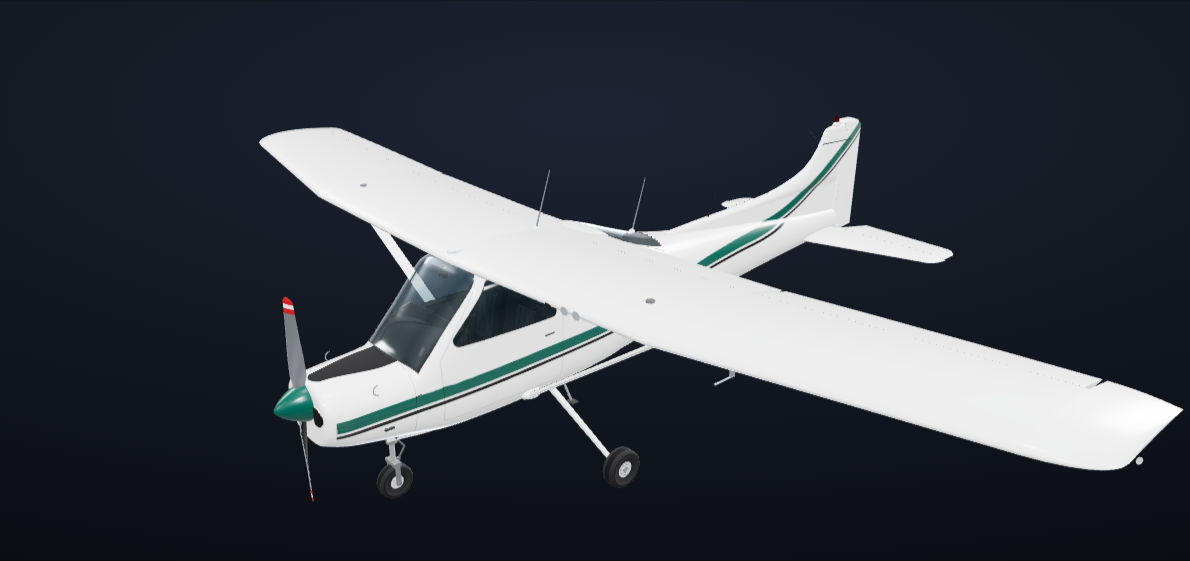
The radio puts out its rated power.
The pilot hears the tower faintly, and the tower hears the pilot faintly.
A conductor that sends and receives radio waves. When the radio transmits, the antenna turns its alternating current into a radio wave. When it receives, a passing radio wave makes a small current in the antenna.
The cable that carries the signal between the radio and its antenna: a center conductor, an insulator around it, a braided shield and an outer jacket.
A resistor that takes all of the radio's power without sending it out as a radio wave, so it tests the radio alone. Shops also call it a dummy load.
When you finish this lesson you can do the four things below. The check at the end asks about each of them.
A comm whip is about a quarter of a wavelength, about 2 feet. The metal skin supplies the rest.
Com 2 on top sits at least half a wavelength from Com 1, about 50 inches.
The most resistance allowed between an antenna base and a metal skin.
Power is coming back from the antenna system instead of going out.
In Routing, Coax, and Databus Wiring you learned how a coax cable is built. This lesson starts from there.
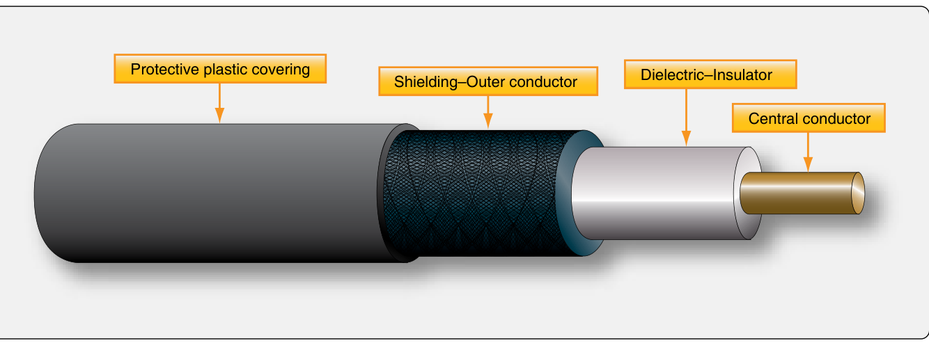
What sets a coax cable's characteristic impedance?
The opposition a coax cable shows to the radio signal, in ohms, set by the size and spacing of its conductors. Aircraft antenna coax is usually about 50 ohms, to match the antenna.
An antenna sends and receives best when its length suits the radio wave. The length that matters is the wavelength.
The number of cycles of the radio wave each second, in hertz. One megahertz (MHz) is one million cycles each second.
The distance a radio wave travels during one cycle. The higher the frequency, the shorter the wavelength.
An antenna is resonant when its length suits the frequency, so the strongest signal goes out and comes in. A half-wave antenna is resonant.
This is the real table from AC 43.13-2B. Select a row to tune the drawing to it.
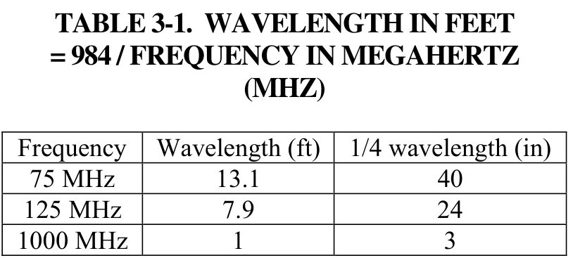
Source: AC 43.13-2B, Table 3-1.
Most aircraft VHF comm antennas are a quarter of a wavelength long. The metal skin under the antenna supplies the missing quarter.
A quarter-wave antenna gets the efficiency of a half-wave antenna by using the conductive skin it is mounted on as the second quarter. That conductive surface is the ground plane. On a metal airplane the skin is the ground plane. On a fabric, wood or composite airplane the installer must build one under the skin, from an aluminum plate, wire mesh, heavy foil or wires spread out from the antenna base.
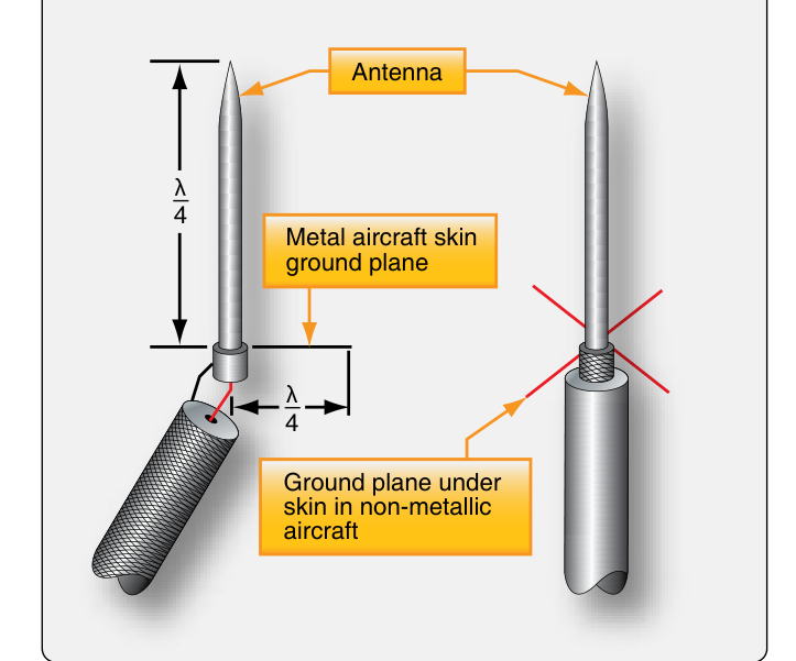
Source: FAA-H-8083-31B, Figure 11-92.
Each number names one part of the figure.
The handbook's name for a quarter-wave antenna that uses the skin as its ground plane. Guglielmo Marconi found in 1895 that a vertical wire, with the other side of his transmitter connected to the earth, sent his signals much farther. On an airplane the skin plays the part of the earth.
Polarization is the direction of the electric field a radio wave carries, and it is set by how the antenna is mounted. A receiving antenna gets the strongest signal when it is mounted the same way as the transmitting antenna.
Mounted up and down, like a comm whip. VHF comm antennas are vertically polarized.
Mounted side to side, like the V-shaped VOR antenna on the fin. VOR and glideslope stations send horizontally polarized signals.
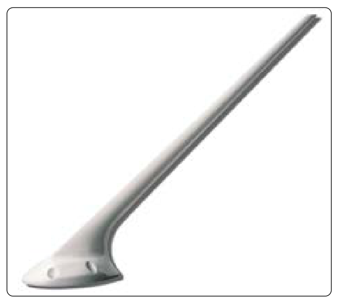
Many vertical and horizontal antennas on aircraft are mounted at a slight angle, called canted. A canted antenna still gets a weak signal, instead of none, when the polarization does not match.
When the antenna system does not accept all of the radio's power, the rest comes back down the coax. VSWR is the number that tells you how much is coming back.
The power going from the radio up the coax toward the antenna.
The power coming back down the coax because the antenna system did not accept it.
A meter in the coax at the radio that reads forward and reflected power.
Voltage standing wave ratio. The forward and reflected waves add and cancel along the coax and make a standing wave. VSWR compares its highest voltage to its lowest. 1.0 is a perfect match. The higher the number, the more power is coming back.
The VSWR limit for an installation comes from its installation or maintenance data. The lab later in this lesson uses 2.0.
Each system has its own antenna, sized for its own band and mounted where it can reach its station. Turn the airplane and select each antenna.
Loading the 3D airplane
Drag to turn the airplane, pinch or scroll to zoom. Select a number, or the antenna itself, to read about it.
Each number is one antenna. Its panel shows the real antenna from AC 43.13-2B.
Where an antenna goes depends on where its signal comes from. Sort each antenna to the side of the airplane it belongs on.
It needs the sky or the stations above and around the airplane.
Tap the bucket where the card belongs. On a computer you can also drag the card.
It needs the ground or the stations below the airplane.
Which bucket does this card belong in?
Photographs: AC 43.13-2B, Figures 3-9, 3-10, 3-12, 3-14, 3-18 and 3-19.
An advisory circular (AC) is an FAA document that describes acceptable methods. AC 43.13-2B covers alterations, and its Chapter 3 covers antenna installation. This is its real page on location. Select a numbered paragraph to read what it means in the shop.
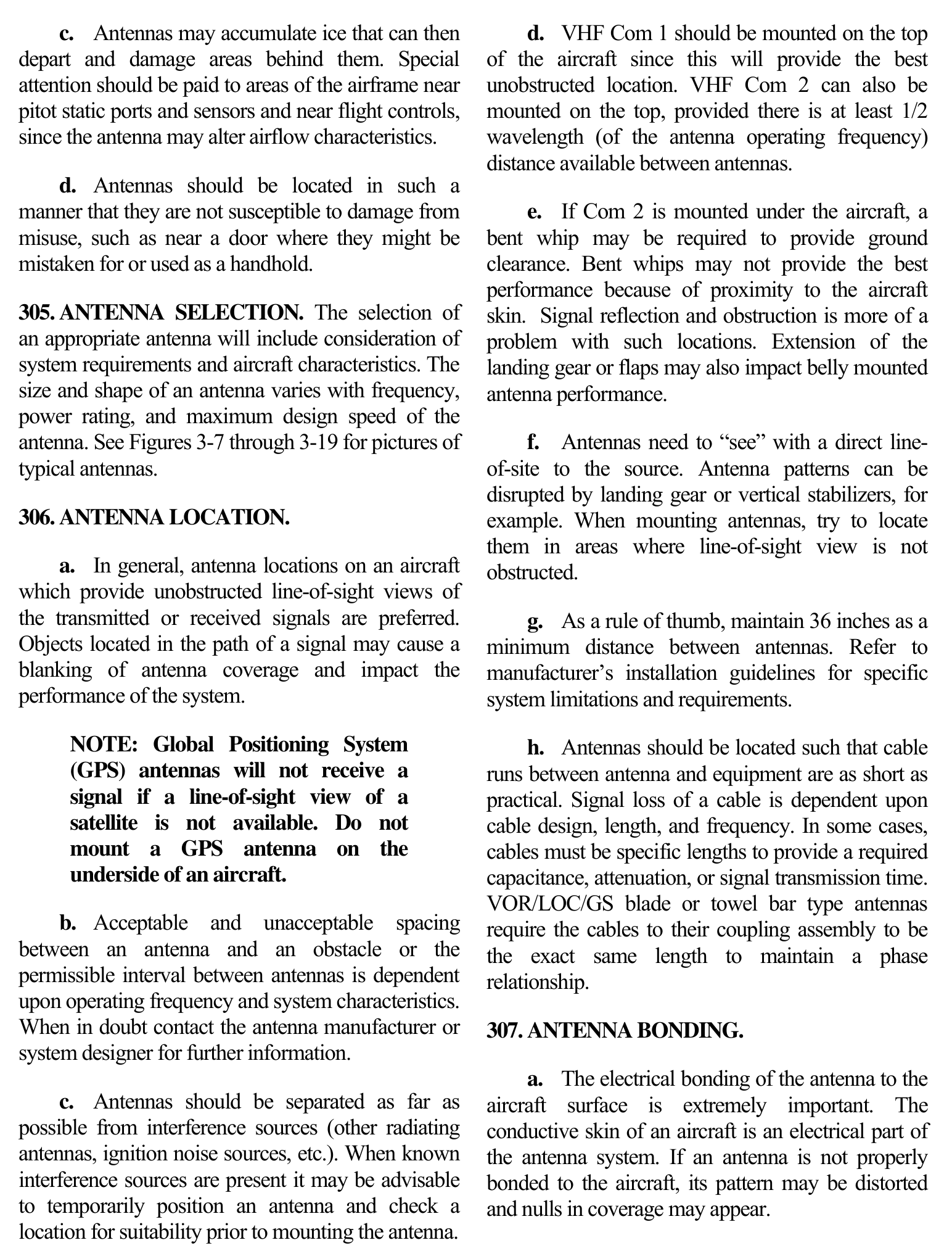
Paragraph
The page is the FAA's own text. Each number sits on one paragraph about where an antenna may go.
In the shop
Source: AC 43.13-2B, Acceptable Methods, Techniques, and Practices, Aircraft Alterations, Chapter 3, page 25.
The owner of the Cessna wants a second comm radio. Its antenna, Com 2, needs a location. Try each spot on the airplane and read the result.
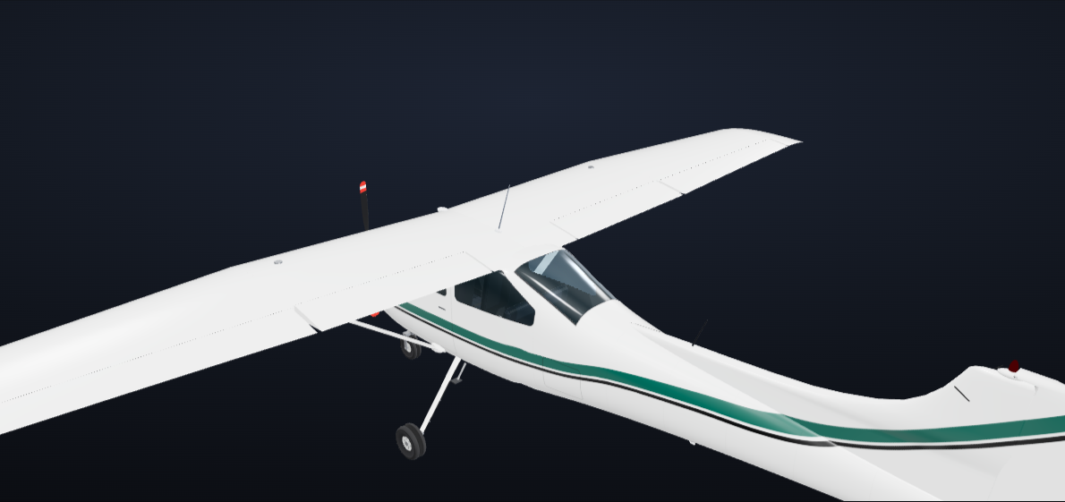 Com 1GPS
Loading the 3D airplane
Select a lettered spot to put Com 2 there. Drag to turn the airplane, pinch or scroll to zoom.
Each letter is a place someone has suggested for Com 2.
The airplane's own approved data and the radio's installation manual decide the final spot. If a hole falls over a stringer, go back to that data. Do not move the antenna on your own.
The coax carries the signal between the radio and the antenna. Its type and length come from the installation manual, and the way it is routed decides how much signal arrives.
Use the cable type the installation manual names. Aircraft antenna coax is about 50 ohms.
Keep runs as short as practical. Transponders, DME and other pulse systems need the precise length the manual gives, and the two cables from a VOR/LOC/GS coupler must be the same length.
Secure the cable about every 2 feet along its whole length. Do not route it with or tie it to other wire bundles.
Bend it no tighter than the installation manual allows; the handbook gives at least 10 times the cable diameter as a general practice. Never kink coax, step on it or drop things on it.
The run meets the installation rules.
Tap the bucket where the card belongs. On a computer you can also drag the card.
The run must be corrected.
Which bucket does this card belong in?
You learned how to terminate and repair coax in Routing, Coax, and Databus Wiring. The same rules apply here.
Sources: FAA-H-8083-31B, Chapter 11, Transmission Lines. AC 43.13-2B, par. 306h. AC 43.13-1B, par. 11-120 and 11-121.
Always follow the antenna manufacturer's instructions. The steps below are the FAA's typical installation, with the real words of AC 43.13-2B for each one.
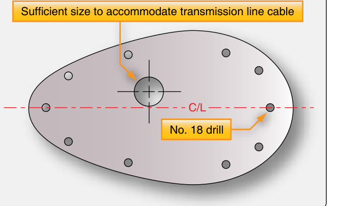
The skin is part of the antenna, so the bond between the base and the skin is part of the antenna too. AC 43.13-2B allows no more than 0.003 ohm between the base plate and the skin.
A milliohm (mΩ) is one thousandth of an ohm, so 0.003 ohm is 3 milliohms.
You used the milliohm meter in Terminations and Bonding. It drives a known current through the joint on one pair of leads and reads the voltage across it on a second pair, so the resistance of its own leads does not count.
Choose an installation above.
If an antenna is not properly bonded, its pattern may be distorted and gaps in its coverage may appear.
Source: AC 43.13-2B, par. 307a, 307b and 309b(7). The three readings are example readings.
An antenna base sits in the airstream and gets rain, washing and deicing fluid. Water that gets under the base or into the connector corrodes the bond and the connector, and the radio turns weak both ways or works until it rains.
The antenna has been lifted off the skin. Each number is one thing to look for.
Found 0 of 6
Sources: AC 43.13-2B, par. 307e and 312.
Two formulas give you the numbers on this lesson's antennas. Both use the frequency in megahertz.
AC 43.13-2B, Table 3-1. Use it for distances, such as spacing.
FAA-H-8083-31B. Use it for the length of an antenna.
The antenna formula comes out about 5 percent shorter than half the wavelength, because the air at the ends of a real antenna makes it act a little longer than it is.
Worked example 1
Worked example 2
Your turn 1
Find the cut length of a quarter-wave comm whip at 127 MHz, in inches.
Your turn 2
Find a quarter wavelength at the transponder's reply frequency, 1090 MHz, in inches.
Two airplanes have radios that are weak both ways. Prove each radio into a test load, measure the antenna system, inspect, repair and measure again.
N590JM's Comm 1 is weak both ways and worse after rain. Before you measure anything, where do you expect the loss?
The lab is optional practice. Continue whenever you are ready.
Back to the Cessna with the weak Comm 1. This is the job, in order.
Five questions, three answers each. Each answer tells you why it is right or wrong.
Each antenna is sized for its band: a wavelength in feet is 984 divided by the frequency in megahertz, and a comm whip is a quarter wave because the metal skin, its ground plane, supplies the rest. You choose a location and coax from the installation data: Com 1 and the GPS on top, Com 2 on top only with half a wavelength of spacing, the cable type and length from the manual. You install an antenna on a doubler, mount it flat, bond it to 0.003 ohm or less and seal it. You inspect the base and connector for water and corrosion, and a high VSWR tells you power is coming back instead of going out.
Length
Location
Install
Inspect
Prove the radio into a test load before you replace it.
Sources: Federal Aviation Administration (FAA) Aviation Maintenance Technician Handbook, Airframe (FAA-H-8083-31B), Chapter 11. Advisory Circular (AC) 43.13-2B, Chapter 3. AC 43.13-1B, Chapter 11. The 3D airplane is the AERO flight simulator's Cessna 172.