AC electricity

AC Principles

A technician sets a multimeter to DC volts, puts the probes on a live 115 volt alternating current (AC) bus, the bar that carries power to the circuits, and reads 0.03 volts. He writes the bus up as dead. A second technician connects an oscilloscope, an instrument that draws a voltage as a line on a screen, and sees a wave that swings 325 volts from bottom to top. The placard, the label beside the bus, says 115 V, 400 Hz.

0.03VVVCOMV
0.03 V
Meter on DC volts
325 V
325 V
Scope, bottom to top
AC BUS115 V 400 Hz
115 V
Placard

FIG 1 One bus, three readings.

An AC voltage takes more than one number to describe. Read the wrong one and you call a live bus dead, or you miss the highest voltage the wiring has to hold.

Learning Objectives

When you finish this lesson you can do the four things below. The check at the end asks about each one.

  1. 1ExplainExplain how a changing magnetic field makes a voltage, and tell AC from DC by the direction the current flows.
  2. 2CalculateCalculate the period of an AC wave from its frequency, and compare 60 Hz shop power with 400 Hz aircraft power.
  3. 3ConvertIdentify peak, peak-to-peak and RMS on a sine wave, convert between them, and state which one the meter shows.
  4. 4ExplainExplain why the transformer, and with it AC, won power distribution.

Key Facts

Induction

A magnet moving in a coil makes a voltage. A magnet sitting still makes none.

Period

Period is 1 divided by frequency. 400 Hz is 2.5 ms.

RMS

The meter on AC volts shows RMS. A 115 V bus peaks at 162.6 V.

Transformer

A transformer raises the voltage, so the same power travels on less current and loses less in the wire.

Lecture Video

Watch the lecture. Continue appears when it ends. You can skip it for now and come back to this page later.

The Aircraft AC Bus

In the Voltage lesson you learned the voltages on an aircraft. Light aircraft run on 14 V or 28 V direct current (DC). Larger aircraft add an AC bus.

AC BUSVHz
FIG 2 The placard beside an aircraft AC bus. Fill in its two numbers.
Quick recall

Which two numbers describe the AC bus on a larger aircraft?

Magnetism

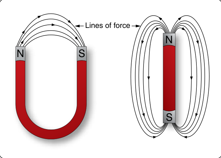
Before you can see where AC comes from, you need magnetism. Magnetism is the property of an object to attract iron and steel. Every magnet has two ends, called poles: a north pole (N) and a south pole (S).

A horseshoe magnet and a bar magnet. Lines of force leave each north pole, curve around, and enter the south pole.
FIG 3 Magnetic field around a horseshoe magnet and a bar magnet. Source: FAA-H-8083-30B, Figure 12-15.

Magnetic Field

The invisible force around a magnet. It is drawn as lines of force that leave the north pole and enter the south pole. The lines never cross. Together they are called magnetic flux.

Electromagnet

A coil of wire, many turns wound side by side, with current through it. The current makes a magnetic field, and the coil gathers it into a north pole and a south pole, like a bar magnet.

Current Makes a Magnetic Field

NSNBatterySwitchCoilCompass
FIG 4 A coil on a battery, with a switch, and a compass beside the end of the coil.

The switch is open. No current flows, so the coil has no magnetic field. The compass points north.

In 1820 the Danish scientist Hans Christian Oersted saw a compass needle swing when he held it near a wire carrying current. It was the first proof that a current makes a magnetic field.

Electromagnetic Induction

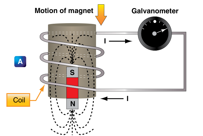
A current makes a magnetic field. It also works the other way: a magnetic field that changes inside a coil makes a voltage in the coil. This is electromagnetic induction, and the voltage it makes is called an induced voltage.

Drag the magnet into the coil and out again. You can also use the buttons.

SNGalvanometerCoilBar magnet
FIG 5 A coil connected to a galvanometer, and a bar magnet you move.

The magnet is out of the coil and still. The needle reads zero.

Galvanometer. A meter with its zero in the middle of the scale, so the needle shows current in either direction.

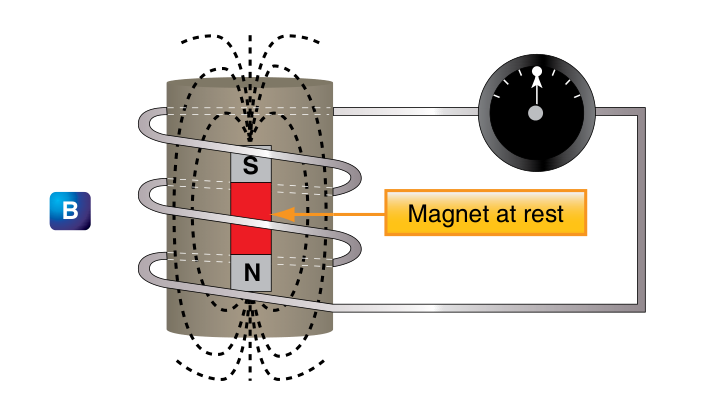
A coil makes a voltage only while the magnetic field through it is changing. A magnet sitting still in a coil makes no voltage.

The Same Test in the FAA Handbook

Panel A: a bar magnet moving down into a coil. The galvanometer needle is swung to one side.

The magnet moves down into the coil. Current flows, and the galvanometer needle swings one way.

Panel B: the magnet sitting still inside the coil. The galvanometer needle is at zero.

The magnet sits inside the coil. Its field passes through the coil but does not change, so the needle reads zero.

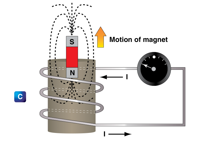
Panel C: the magnet moving up out of the coil. The galvanometer needle is swung the other way.

The magnet moves up out of the coil. The current reverses, and the needle swings the other way.

FIG 6 Inducing a current flow. Source: FAA-H-8083-30B, Figure 12-104.

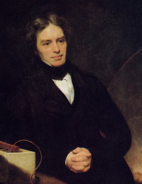
Michael Faraday

The English scientist Michael Faraday discovered electromagnetic induction in 1831. The unit of capacitance, the farad, which you meet in the next lesson, is named for him.

Painted portrait of Michael Faraday in a dark coat and a white collar, his hands folded, with electrical apparatus and a wire on the table beside him.
Michael Faraday, oil painting by Thomas Phillips, 1842. Public domain, via Wikimedia Commons.
1831
Michael Faraday (1791 to 1867)

Faraday was the son of a blacksmith and had little schooling. As a bookbinder's apprentice in London he read the science books he bound, and in 1813 he became an assistant at the Royal Institution. In 1831 he moved a magnet in and out of a coil of wire and measured a current in the coil. The same year he built the first generator, a copper disk turned between the poles of a magnet.

FAA-H-8083-30B, Aviation Maintenance Technician Handbook, General. Chapter 12

Inductance

Characteristics of Inductance

Michael Faraday discovered that by moving a magnet through a coil of wire, a voltage was induced across the coil. If a complete circuit was provided, then a current was also induced. The amount of induced voltage is directly proportional to the rate of change of the magnetic field with respect to the coil.

Source: FAA-H-8083-30B, page 12-56. Text as printed.

Select a highlighted phrase to read what it means.

Select a phrase in the handbook text.

The AC Generator

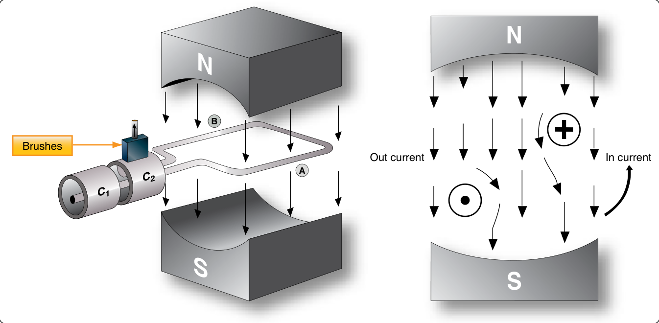
A generator is a machine that turns motion into voltage by induction. The simplest one is a loop of wire turned between the north and south poles of a magnet. A generator that makes alternating current is called an alternator. The alternator the engine turns on a light aircraft works on the same principle.

Drag to turn the view. Select a number to read about that part.

Loop at 0°Speed Medium

The loop is stopped. Select Turn the loop.

Select a number on the model.

FIG 7 A simple generator, drawn after FAA-H-8083-30B, Figure 12-108. The meter under the model has its zero in the middle.

Factors That Set the Voltage

More turns of wire

More wire cutting the field makes more voltage.

A stronger magnet

A stronger field makes more voltage.

Faster turning

The sides cut the field faster and make more voltage.

The Sine Wave

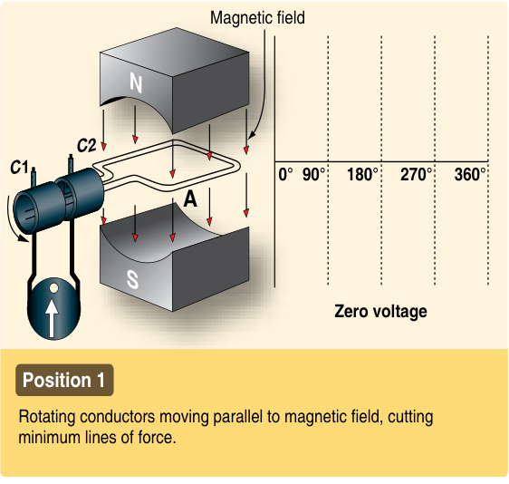
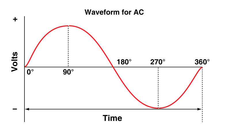
As the loop turns, its voltage rises and falls in a smooth curve called a sine wave. The FAA handbook follows one side of the loop, side A, through one full turn of 360 degrees (°) in five positions. A quarter turn is 90°.

NSAB0°90°180°270°360°+−Voltage of the loop
FIG 8 Left: the loop seen from its end, turning between the poles. Right: the voltage it makes at each angle.
FAA drawing, Position 1: the loop flat between the N and S poles, and a graph with no voltage yet at 0 degrees.
Position 1

0°. Side A moves along the lines of force and cuts none of them. Zero voltage.

Source: FAA-H-8083-30B, Figure 12-109.

Sine Wave

The curve a turning loop makes. The line across the middle is time, or degrees of rotation. The height above or below the line is the voltage at that instant, positive above and negative below.

Direct Current and Alternating Current

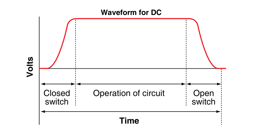
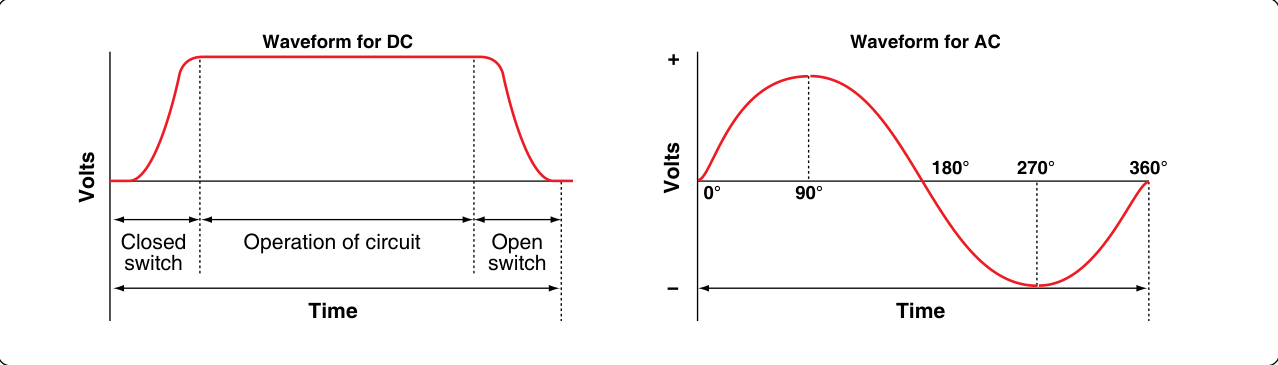
Direct current is electricity that only moves in one direction. Alternating current reverses direction in cycles: the electrons shift back and forth in place while the energy moves along the wire. You call a supply AC or DC by the way its current flows, not by where it comes from.

The DC graph of volts against time: it rises when the switch closes, stays level while the circuit operates, and falls when the switch opens.The AC graph of volts against time: it rises to a positive peak at 90 degrees, crosses zero at 180, reaches a negative peak at 270 and returns to zero at 360.Two graphs of volts against time. DC rises when the switch closes, stays level while the circuit operates, and falls when the switch opens. AC rises to a positive peak at 90 degrees, crosses zero at 180, reaches a negative peak at 270 and returns to zero at 360.
FIG 9 DC rises when the switch closes and stays at one level in one direction. AC changes direction at regular intervals. Source: FAA-H-8083-30B, Figure 12-103.

AC or DC

Direct current

One direction

Tap the bucket where the card belongs. On a computer you can also drag the card.

Alternating current

Reverses in cycles

Which bucket does this card belong in?

Cycle, Frequency and Period

One complete pattern of the wave, up, down and back to the start, is one cycle. The number of cycles in one second is the frequency. The time one cycle takes is the period.

Cycle

One complete pattern of the wave. It has two alternations, a positive half and a negative half.

Frequency

Cycles per second, in hertz (Hz). The FAA handbook and older manuals also write "cycles", as in 400-cycle power.

Period

The time for one cycle, in seconds or milliseconds (ms). One millisecond is one thousandth of a second.

The Live Sine

The screen shows 20 milliseconds from left to right. Select 60 Hz, then 400 Hz, and count the cycles that fit in the same 20 ms: just over one at 60 Hz, eight at 400 Hz.

10.0 ms
20 V
f = 1 / T
100 Hz
Period 10.0 ms on a 20 ms window.
V 20 ms
Peak-to-peak
20 V
Peak
10 V
RMS
7.1 V

Period of Shop Power and Aircraft Power

Frequency and period are opposites: the higher the frequency, the shorter the period. Divide 1 by the frequency to get the period.

period = 1 ÷ frequency
60 Hz
Wall outlets in the shop
400 Hz
Aircraft AC bus and ground power

A ground power unit, the cart that powers a parked aircraft, supplies 400 Hz AC (FAA-H-8083-30B, Chapter 1).

60 Hz

  1. period = 1 ÷ 60 Hz
  2. = 0.0167 seconds
  3. Multiply by 1,000 to change seconds to milliseconds: 16.7 ms

400 Hz

  1. period = 1 ÷ 400 Hz
  2. = 0.0025 seconds
  3. = 2.5 ms
Check your answer400 Hz is about 6.7 times 60 Hz, and 2.5 ms is about one 6.7th of 16.7 ms. Each cycle reverses direction twice, so 400 Hz power reverses 800 times a second.
Your turn

Building power in Europe is 50 Hz. What is its period in milliseconds?

ms

Peak, Peak-to-Peak and RMS

An AC voltage changes every instant, so it takes more than one number to describe it. The FAA handbook names three values: instantaneous, peak and effective, also called RMS. Peak-to-peak is a fourth number you read on a scope.

Select each value to mark it on the wave.

0PeakPeak-to-peakRMS, 0.707 × peak
FIG 10 One cycle of a sine wave.

Select a value above.

Change the Height

Move the peak-to-peak slider. The wave grows taller, and the three numbers follow it.

10.0 ms
20 V
f = 1 / T
100 Hz
Period 10.0 ms on a 20 ms window.
V 20 ms
Peak-to-peak
20 V
Peak
10 V
RMS
7.1 V

Effective Value (RMS)

RMS stands for root mean square, the math used to find it. The FAA handbook calls it the effective value, because it measures the heating effect of the wave. The RMS value of an AC voltage is the DC voltage that makes the same heat in the same resistor.

Two identical 100 Ω heaters. Heater A is on a 115 V AC bus whose wave peaks at 162.6 V. Set the DC supply until heater B glows exactly as hot as heater A.

Heater AHeater B115 V AC busDC supply
FIG 11 Two identical heaters, drawn after FAA-H-8083-30B, Figure 12-113.
Heater A132 W
Heater B0 W
40.0 V

Set the DC supply until heater B glows exactly as hot as heater A.

P = E² ÷ R, from the Ohm's Law lesson: 115 × 115 ÷ 100 = 132 W.

FAA-H-8083-30B, Aviation Maintenance Technician Handbook, General. Chapter 12

Effective Value

Values of Alternating Current

The effective value is also known as the RMS value or root mean square, which refers to the mathematical process by which the value is derived. Most AC voltmeters display the effective or RMS value when used. The effective value is less than the maximum value, being equal to .707 times the maximum value.

In the study of AC, any values given for current or voltage are assumed to be effective values unless otherwise specified.

Source: FAA-H-8083-30B, page 12-49. Text as printed.

Select a highlighted phrase to read what it means.

Select a phrase in the handbook text.

Converting RMS, Peak and Peak-to-Peak

For a sine wave, and only a sine wave, you convert with two numbers, 0.707 and 1.414. The 115 V on the placard is RMS.

RMS = 0.707 × peak
peak = 1.414 × RMS
peak-to-peak = 2 × peak
  1. 115 V RMSWhat the meter shows
  2. 162.6 V peakZero line to tip
  3. 325.2 V peak-to-peakTip to tip, what the scope showed on the first page

Check any conversion. If an RMS answer comes out larger than the peak, you multiplied when you should have divided.

WarningA 115 V RMS bus reaches 162.6 V at its peak twice every cycle. The insulation and the shock hazard are set by the peak, not by the number on the meter.

The 26 V Instrument Bus

Many aircraft also have a 26 V, 400 Hz AC bus for instruments. Work each card, then select it to check.

Prediction

A scope shows an AC sine wave measuring 200 V peak-to-peak. What does a meter on AC volts read?

The Transformer

A transformer is two coils of wire wound on one iron core, the frame the coils sit on. AC in the first coil, the primary, makes a magnetic field that keeps changing. The core carries the changing field to the second coil, the secondary, and induces a voltage there. More turns on the secondary steps the voltage up; fewer turns steps it down.

PrimarySecondaryIron coreLampMeter
FIG 12 A transformer with a lamp and a center-zero meter on its secondary.

Select a source for the primary.

A transformer needs a changing field. Steady DC makes a steady field, and a steady field induces nothing.
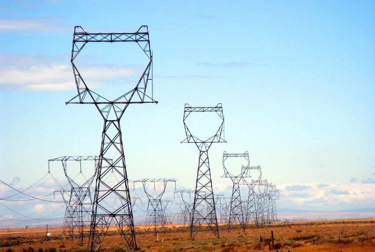
FIG 13 A power line uses a transformer at each end: one steps the voltage up for the long run, and one steps it back down for the user. A transformer needs a changing field, so this chain works only on AC.

Distribution Voltage and Wire Loss

Every wire has resistance, so current through it turns some power into heat. The loss depends on the current. For the same power, a higher voltage needs less current, because current is power divided by voltage, I = P ÷ E.

about 36 A
1,000 W at 28 V DC

1,000 ÷ 28 = 35.7 A

under 9 A
1,000 W at 115 V AC

1,000 ÷ 115 = 8.7 A. Less current rides on smaller, lighter wire.

Sending 12,000 W to a Town

A generator sends 12,000 W to a town through a feeder, the pair of wires between them, with 0.2 Ω of resistance in all. Select a line voltage.

GeneratorTownFeeder, 0.2 Ω in all12,000 W delivered
FIG 14 The wire glows with the heat it loses.
  1. CurrentI = P ÷ E
  2. Drop in the wiredrop = I × R
  3. Lossloss = drop × I
CautionNever put in a smaller wire size than the drawing calls for because it fits the terminal. The size was chosen for the current and the length of that run. Undersized wire runs hot inside a bundle where nobody can see it.

The War of the Currents

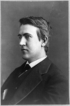
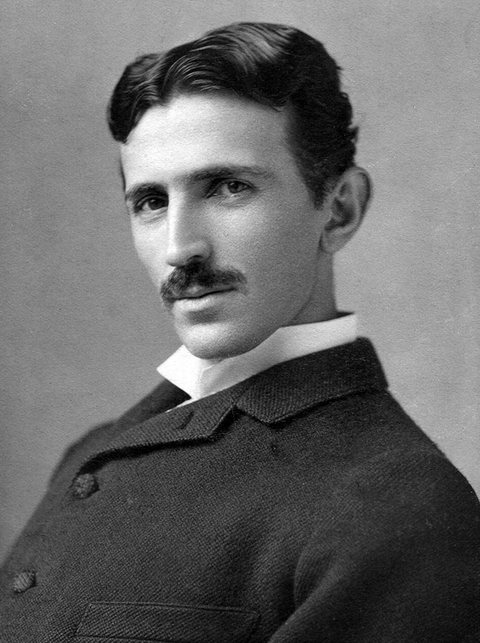
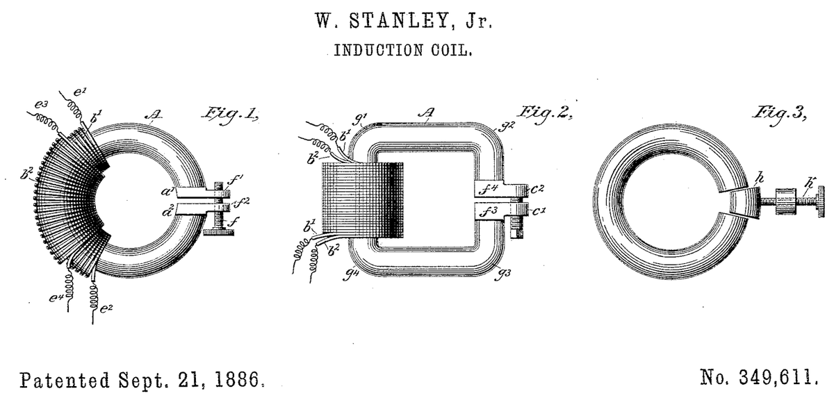
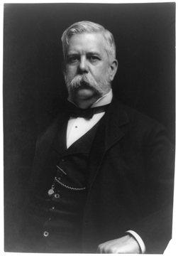
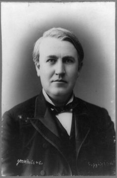
In the 1880s Thomas Edison's direct current (DC) and George Westinghouse's alternating current (AC) fought to light American cities. The contest is called the war of the currents, and the transformer decided it.

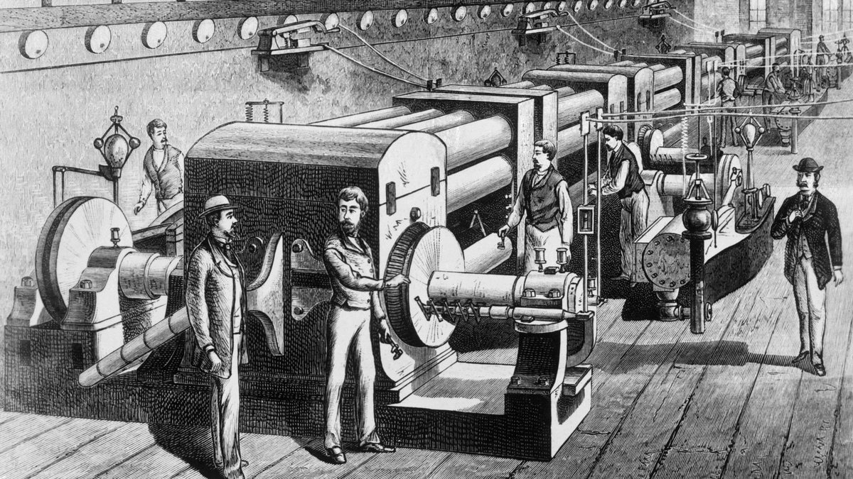
Black-and-white engraving of a long machine room with a row of large drum-shaped dynamos coupled to engines, men in suits and bowler hats standing beside them, and round lamps along the wall.
Black-and-white photograph of a young man in profile facing left, with thick tousled hair, a dark coat, a white collar and a dark bow tie.1882Edison, DC

Pearl Street Station

On 4 September 1882, Thomas Edison (1847 to 1931) started his Pearl Street Station in lower Manhattan. Steam engines turned its dynamos, the generators of the day, and sent 110 V DC to about 400 lamps for fewer than 100 customers. At 110 V the current was high, so the copper wire was costly and lost power to heat. A DC station could serve customers only within about a mile.

Chapter 1 of 10

The dynamo room at Pearl Street Station, engraving, Scientific American, 26 August 1882. Deutsches Museum. Public domain, via Wikimedia Commons. Portrait: Thomas Edison, photograph by Emil P. Spahn, 1880. Library of Congress. Public domain, via Wikimedia Commons.
AC won because a transformer can raise the voltage for a long line and lower it again at the other end. Higher voltage means less current for the same power, and less current loses less in the wire. That is why an aircraft carries its big loads on the 115 V AC bus: the current is about a quarter of what 28 V would need.
Check your understanding

Edison's DC stations could serve only the area close around them. Which reason explains that limit?

Sources: IEEE Milestones, Pearl Street Station, 1882, Alternating Current Electrification, 1886, and Adams Hydroelectric Generating Plant, 1895; ETHW, "Early Electrification of Buffalo"; Thomas A. Edison Papers, Rutgers University; T. Reynolds and T. Bernstein, "Edison and 'The Chair'," IEEE Technology and Society Magazine, March 1989; N. Tesla, "My Inventions," Electrical Experimenter, May 1919; The Electrical World, 11 August 1888 and 28 November 1896; U.S. Department of Energy, "The War of the Currents"; Tesla Science Center at Wardenclyffe; FAA-H-8083-31B, pages 9-27 and 9-59; The New York Times, 14 November 2007.

Peak, RMS and the Meter Lab

A 26 V, 400 Hz instrument bus feeds a lamp. You read it with the meter on AC volts and on DC volts, at 400 Hz and at 60 Hz, and then with a square wave, a wave that jumps between its top and bottom values instead of curving. On the dial, AC volts is marked V~ and DC volts V⎓.

Prediction

The meter is on DC volts, across this live 26 V, 400 Hz bus. What will it read?

Then work the four steps in the panel beside the circuit. Each step checks itself, and the lab records your readings.

Steps done: 0 of 4. Your readings are recorded in the lab. Open in a new tab

Applying the Procedure

The bus on the first page was live. Follow these steps to check an AC bus and read it the right way.

  1. Read the placard or the wiring diagram. This bus is 115 V AC at 400 Hz.
  2. Set the meter's dial to AC volts (V~), with the red lead in the V jack and the black lead in COM.
  3. Put the probes across the bus. The meter reads 115 V. That is the RMS value, the number on the placard.
  4. If a scope is on the bus, expect 162.6 V peak and 325.2 V peak-to-peak. All three numbers describe the same wave.
  5. Record the bus as normal. The 0.03 V reading showed only that the meter was on DC volts: on DC volts the meter averages the wave, and the two halves cancel.
0.03VVVCOMVAC busGround
FIG 15 The meter on the same bus. Turn the dial.

On DC volts (V⎓) the meter averages the wave. The two halves cancel, and it reads 0.03 V on a live bus.

CautionMeasure a live bus only when the maintenance manual allows it, with test leads rated for the voltage.

Check

Five questions, three answers each. Each answer tells you why it is right or wrong.

4 of 5
Needed to pass
  1. 1ExplainExplain how a changing magnetic field makes a voltage, and tell AC from DC by the direction the current flows.
  2. 2CalculateCalculate the period of an AC wave from its frequency, and compare 60 Hz shop power with 400 Hz aircraft power.
  3. 3ConvertIdentify peak, peak-to-peak and RMS on a sine wave, convert between them, and state which one the meter shows.
  4. 4ExplainExplain why the transformer, and with it AC, won power distribution.
Question 1 of 5

0 of 5
Results Results
From this lesson
  1. 01A changing magnetic field makes a voltage. AC reverses; DC flows one way.
  2. 02Period is 1 ÷ frequency. 400 Hz is 2.5 ms.
  3. 03The meter shows RMS. Peak is 1.414 × RMS. Peak-to-peak is 2 × peak.
  4. 04A transformer needs a changing field. Higher voltage means less current and less loss.
Select any row to re-read its feedback.

Field Card

A magnetic field that changes inside a coil makes a voltage; a turning loop makes that voltage rise, fall and reverse in a sine wave, which is alternating current. Frequency counts the cycles each second, and the period is 1 divided by the frequency. The meter on AC volts shows RMS, and the wave peaks at 1.414 times that. A transformer needs a changing field, so only AC can be stepped up for the long run, and the higher voltage carries the same power on less current with less loss.

You can now explain that a changing magnetic field makes voltage, and call AC and DC by the direction of flow.

Changing fieldvoltage
Magnet at rest0 V
DCone direction
ACreverses in cycles

You can now turn a frequency into a period.

period1 ÷ frequency
60 Hz16.7 ms
400 Hz2.5 ms
400 Hz800 reversals a second

You can now read a 115 V bus as RMS, peak and peak-to-peak.

Meter on V~RMS
Peak1.414 × RMS
115 V162.6 V peak
Peak-to-peak325.2 V

You can now explain why the transformer and AC won.

Transformerneeds a changing field
Higher voltageless current
Less currentless wire loss
1,000 W36 A at 28 V, 8.7 A at 115 V

Set the meter to V~ before you trust a reading on an AC bus.

Sources: FAA-H-8083-30B, Aviation Maintenance Technician Handbook, General (2023), Chapter 12 (Magnetism, Electromagnetism, Alternating Current and Voltage, Generator Principles, Cycle and Frequency, Values of Alternating Current, Inductance) and Chapter 1 (ground power units); Encyclopaedia Britannica (Michael Faraday, Nikola Tesla, George Westinghouse); U.S. Department of Energy, The War of the Currents.